Posts

Recent research suggests that ECG wearables devices (such as smart watches) are now medically suitable for providing predictive insights into serious heart conditions such as atrial fibrillation (A-Fib). These advancements have been facilitated by the availability of low-cost microcontrollers offering algorithmic functionality, allowing developers to implement wearables with excellent battery life and edge-based real-time data analysis.

Although the international research community has produced many innovative high-performance ECG and PPG biomedical algorithms, these are unfortunately limited to offline clinical analysis in Matlab or Python. As such, very little emphasis has been placed on building commercial real-time wearables algorithms on microcontrollers, leading manufacturers to conduct the research themselves and to design suitable candidates. 

This is further complicated by the requirement of manufacturers on how they will implement a developed algorithm in real-time on a low-cost microcontroller and still achieve decent battery life.

Arm Cortex-M microcontrollers

Over 90% of the microcontrollers used in the smart product market are powered by so-called Arm Cortex-M processors that offer a combination of high algorithmic performance, low-power and security. The Arm Cortex-M4 is a very popular choice with hundreds of silicon vendors (including ST, TI, NXP, ADI, Nordic, Microchip, Renesas), as it offers DSP (digital signal processing) functionality traditionally found in more expensive devices and is low-power.

The Cortex-M4F device offers floating point support, helping with RAD (rapid application development) as designs can be easily ported from Matlab/Python to C without the need of performing a detailed quantisation arithmetic analysis. As such, a design cycle can be cut from months to weeks, offering organisations a significant cost saving.

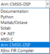
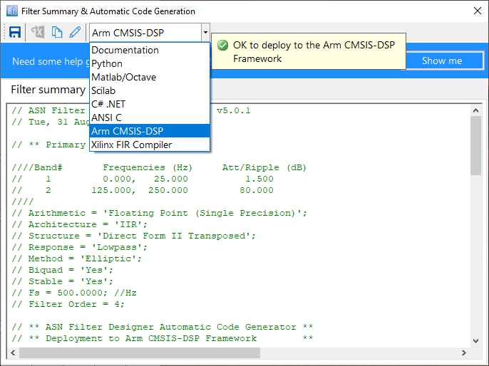
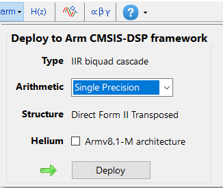
Arm and its rich ecosystem of partners provide developers with easy-to-use tooling and tried and tested software libraries, such as the CMSIS-DSP and CMSIS-NN frameworks and ASN’s DSP filtering library for algorithm development and machine learning.

FDA compliance

The AHA (American Heart Association) provides developers with guidelines for developing FDA-compliant ECG monitoring products. These are broken down into the following three categories: 

  1. Diagnostic: 0.05Hz -150Hz
  2. Ambulatory (wearables): 0.67Hz – 40Hz
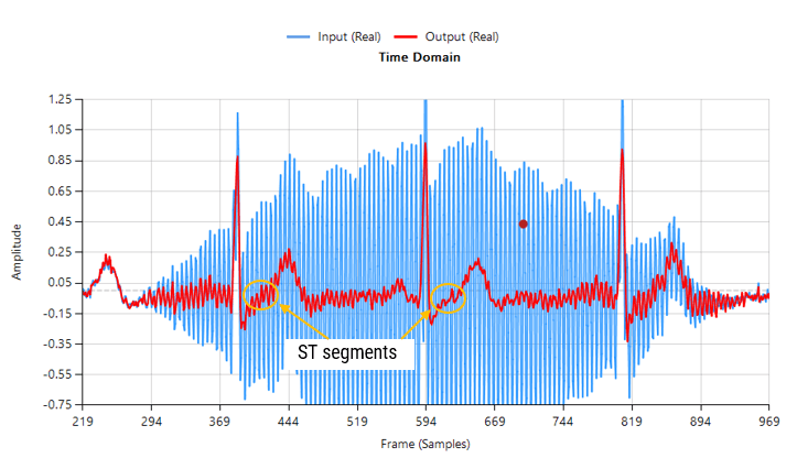
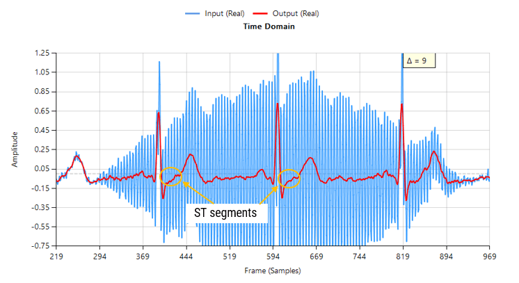
  3. ST segment: 0.05Hz

The ECG measurements must be FDA compliant with IEC 60601-2 2-47 standards for ambulatory ECG, but what are the criteria and challenges?

Challenges with ECG/PPG measurements

Modelling the QRS complex found in ECG data is extremely difficult, as to date there is no concrete model available.  This is further complicated by the variety of ECG data depending on the position of the lead on the patient’s body and illnesses. The following list summaries the typical challenges faced by algorithm developers:

  1. Accurate baseline wander (BLW) removal remains one of the most challenging topics in ECG analysis.
  2. The BLW must be removed for accurate clinical analysis.
  3. BLW manifests itself as low-frequency ‘wander’ (typically <0.5Hz) from EMG and torso movement.
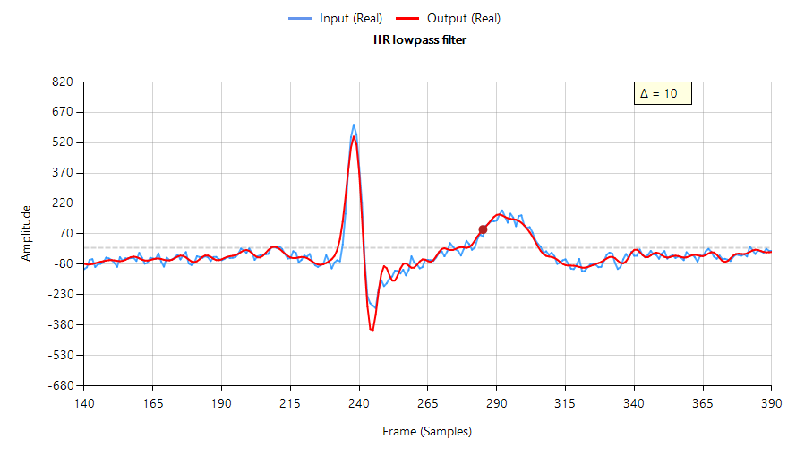
  4. QRS width widening and amplitude distortion due to filtering invalidates clinical analysis.
  5. Reducing EMG and measurement noise without altering the temporal biomedical relationships of the ECG signal.
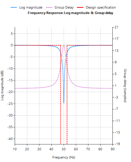
  6. 50/60Hz powerline interference can swamp the ECG signal – this is primarily attributed to pickup by the long high impedance measurement cables. This is typically problematic for extended bandwidth wearable applications that go beyond 40Hz.
  7. Glitches, sudden movement and poor sensor contact with the skin: This is related to BLW, but usually manifests itself as abrupt glitches in the ECG measurement data. The correction algorithm must discriminate between these undesirable events and normal behaviour.
  8. IEC 60601-2 2-47 frequency response specifications:
    • Bandwidth: 0.67Hz – 40Hz.
    • Passband ripple: < ±0.5dB
    • Maximum ±10% amplitude error: most biomedical SoCs make use of a Sigma-Delta ADC, leading to amplitude droop.

Shortcomings with ECG/PPG algorithms

A mentioned in the previous section, much research has been conducted over the years with mixed results. The main shortcomings of these methods are summarised below:

  1. Computationally heavy: most algorithms have been designed for research in Matlab and not for real-time, e.g. wavelets have excellent performance but have high computational cost, leading to poor battery life and the need for an expensive processor.
  2. Large latency and warping: digital filtering chain introduces large latency, computational cost and can warp the characteristics of the biomedical features.
  3. Overlapping frequencies: there are many examples of unwanted noise overlapping the delicate ECG data, hence the popularity of time-frequency analysis, such as wavelets.
  4. Mixed results regarding BLW removal: spline removal is excellent, but it has high computational cost and has the added difficulty of finding good correction points between the QRS complexes. Linear phase FIR filtering is a good compromise but has very high computational cost (typically >1000 filter coefficients) due to the high sampling rate to cut-off frequency ratio. Non-linear phase IIR filter has low computational cost, but warps the ECG features, and is therefore unsuitable for clinical analysis.
  5. AI based kernel filters: ‘black box filter’ based on massive training data. Moderate implementation cost with performance dependent on the variety of training data, leading to unpredictable results in some cases.
  6. PPG analysis: has the added difficulty of eliminating motion from the measurement data, such as when walking or running. Although a range of tentative algorithms has been proposed by various researchers using accelerometer measurement data to correct the PPG data, very few commercial solutions are currently based on this technology.

It would seem that ECG and PPG analysis has some major obstacles to overcome, especially when considering how to deploy the algorithms on low-power microcontrollers.

The future: ASN’s real-time RCF algorithm and Advanced Analytics

Together with cardiologists from Medisch Spectrum Twente, ASN’s advanced analytics team developed the RCF (retrospective collaborative filtering) algorithm that uses time-frequency analysis to enhance the ECG data in real-time.

The essence of RCF algorithm centres around a highly optimised set of polynomial cleaning filters with different frequency characteristics that are applied to different segments of the QRS complex for enhancement. This has some synergy with wavelets, but it does not suffer from the computational burden associated with wavelet analysis.

The polynomial filters are peak preserving, meaning that they preserve the delicate biomedical peaks while smoothing out the unwanted noise/ripple. The polynomial fitting operation also overcomes the challenge of overlapping frequency content, as data within a specified region is smoothed out by the relevant filter.

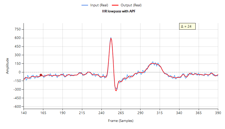
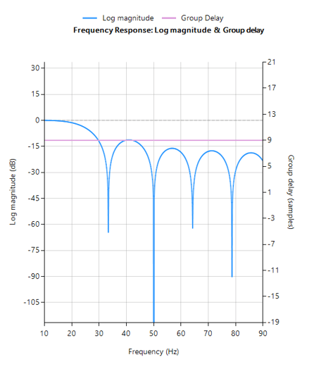
RCF is further strengthened by the BLW killer IP block that implements a highly computationally efficient linear phase 0.67Hz highpass filter. The net effect is an FDA-compliant signal chain suitable for clinical analysis. The complete signal chain is extremely computationally efficient, and as such is suitable for Arm’s popular M3 and M4 Cortex-M processor families.

Real-time ECG feature extraction

The ECG waveform can be split up into segments, where each wave or segment represents a certain event in the cardiac cycle, as shown below:

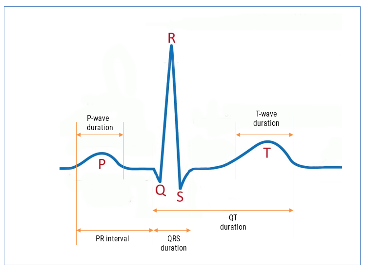
As seen, the biomedical features are designated P, Q, R, S, T that define points in time within the cardiac cycle. The RCF algorithm is further strengthened with our state-of-the-art AAE (Advanced Analytics Engine) that automatically cleans and find these features for clinical analysis.

AAE supported analytics

  1. P-wave duration
  2. PR interval
  3. QRS duration
  4. QT duration (Bazett algorithm used for QTc)
  5. HR (RR interval)
  6. HRV (rMSSD algorithm used)

Armed with the real-time features, an ML model can be trained and provide valuable insights into patient health running on an edge processor inside a wearable device.

A-Fib

Atrial fibrillation (A-Fib) is the most frequent cardiac arrhythmia, affecting millions of people worldwide. An arrhythmia is when the heart beats too slowly, too fast, or in an irregular way. Signs of A-Fib are an irregular beating pattern and no p-waves. Our AAE provides developers with all of the relevant features needed to build an ML model for robust A-Fib detection.

Let us help you build your product

By combining advanced low-power processor technology, advanced mathematical algorithmic concepts and medical knowledge, our solution provides developers with an easy way of building wearable products for medical use. The high accuracy of our Advanced Analytics Engine (AAE) has been verified by cardiologists, and can be used with an additional ML model or standalone to provide people with valuable insights into potentially fatal health conditions, such as A-Fib without the need for an expensive medical examination at a hospital.

ASN’s ECG algorithmic solutions are ideal for building next generation ECG and PPG wearable products on Arm Cortex-M microcontrollers (e.g. STM32F4, MAX32660) and bio-sensor SoCs (MAX86150). These algorithms can be easily used with industry standard biomedical AFEs, such as: MAX30003, AFE4500 and AFE4950.

Please contact us for more information and to arrange an evaluation.

Author

  • Dr. Sanjeev Sarpal

    Sanjeev is an AIoT visionary and expert in signals and systems with a track record of successfully developing over 25 commercial products. He is an Arm Ambassador and advises top international blue chip companies on their AIoT solutions and strategies for I4.0, telemedicine, smart healthcare, smart grids and smart buildings.

Although the design of FIR filters with linear phase is an easy task. This is certainly not true for IIR filters that usually have a highly non-linear phase response, especially around the filter’s cut-off frequencies. This article discusses the characteristics needed for a digital filter to have linear phase, and how an IIR filter’s passband phase can be modified in order to achieve linear phase using all-pass equalisation filters.

Why do we need linear phase filters?

Digital filters with linear phase have the advantage of delaying all frequency components by the same amount, i.e. they preserve the input signal’s phase relationships. This preservation of phase means that the filtered signal retains the shape of the original input signal. This characteristic is essential for audio applications as the signal shape is paramount for maintaining high fidelity in the filtered audio. Yet another application area that requires this, is ECG biomedical waveform analysis, as any artefacts introduced by the filter may be misinterpreted as heart anomalies.

The following plot shows the filtering performance of a Chebyshev type I lowpass IIR on ECG data – input waveform (shown in blue) shifted by 10 samples (\(\small \Delta=10\)) to approximately compensate for the filter’s group delay. Notice that the filtered signal (shown in red) has attenuated, broadened and added oscillations around the ECG peak, which is undesirable.

Figure 1: IIR lowpass filtering result with phase distortion

In order for a digital filter to have linear phase, its impulse response must have conjugate-even or conjugate-odd symmetry about its midpoint. This is readily seen for an FIR filter,

\(\displaystyle H(z)=\sum\limits_{k=0}^{L-1} b_k z^{-k}\tag{1} \)

With the following constraint on its coefficients,

\(\displaystyle b_k=\pm\, b^{\ast}_{L-1-k}\tag{2} \)

which leads to,

\(\displaystyle z^{L-1}H(z) = \pm\, H^\ast (1/z^\ast)\tag{3} \)

Analysing Eqn. 3, we see that roots (zeros) of \(\small H(z)\) must also be the zeros of  \(\small H^\ast (1/z^\ast)\). This means that the roots of \(\small H(z)\) must occur in conjugate reciprocal pairs, i.e.  if \(\small z_k\) is a zero of \(\small H(z)\), then \(\small H^\ast (1/z^\ast)\) must also be a zero.

Why IIR filters do not have linear phase

A digital filter is said to be bounded input, bounded output stable, or BIBO stable, if every bounded input gives rise to a bounded output. All IIR filters have either poles or both poles and zeros, and must be BIBO stable, i.e.

\(\displaystyle \sum_{k=0}^{\infty}\left|h(k)\right|<\infty \tag{4}\)

Where, \(\small h(k)\) is the filter’s impulse response. Analyzing Eqn. 4, it should be clear that the BIBO stability criterion will only be satisfied if the system’s poles lie inside the unit circle, since the system’s ROC (region of convergence) must include the unit circle. Consequently, it is sufficient to say that a bounded input signal will always produce a bounded output signal if all the poles lie inside the unit circle.

The zeros on the other hand, are not constrained by this requirement, and as a consequence may lie anywhere on z-plane, since they do not directly affect system stability. Therefore, a system stability analysis may be undertaken by firstly calculating the roots of the transfer function (i.e., roots of the numerator and denominator polynomials) and then plotting the corresponding poles and zeros upon the z-plane.

Applying the developed logic to the poles of an IIR filter, we now arrive at a very important conclusion on why IIR filters cannot have linear phase.

A BIBO stable filter must have its poles within the unit circle, and as such in order to get linear phase, an IIR would need conjugate reciprocal poles outside of the unit circle, making it BIBO unstable.

Based upon this statement, it would seem that it’s not possible to design an IIR to have linear phase. However, a discussed below, phase equalisation filters can be used to linearise the passband phase response.

Phase linearisation with all-pass filters

All-pass phase linearisation filters (equalisers) are a well-established method of altering a filter’s phase response while not affecting its magnitude response. A second order (Biquad) all-pass filter is defined as:

\( A(z)=\Large\frac{r^2-2rcos \left( \frac{2\pi f_c}{fs}\right) z^{-1}+z^{-2}}{1-2rcos \left( \frac{2\pi f_c}{fs}\right)z^{-1}+r^2 z^{-2}}\tag{5} \)

Where, \(\small f_c\) is the centre frequency, \(\small r\) is radius of the poles and \(\small f_s\) is the sampling frequency. Notice how the numerator and denominator coefficients are arranged as a mirror image pair of one another.  The mirror image property is what gives the all-pass filter its desirable property, namely allowing the designer to alter the phase response while keeping the magnitude response constant or flat over the complete frequency spectrum.

Cascading an APF (all-pass filter) equalisation cascade (comprised of multiple APFs) with an IIR filter, the basic idea is that we only need to linearise the phase response the passband region. The other regions, such as the transition band and stopband may be ignored, as any non-linearities in these regions are of little interest to the overall filtering result.

The challenge

The APF cascade sounds like an ideal compromise for this challenge, but in truth a significant amount of time and very careful fine-tuning of the APF positions is required in order to achieve an acceptable result. Each APF has two variables: \(\small f_c\) and \(\small r\) that need to be optimised, which complicates the solution. This is further complicated by the fact that the more APF stages that are added to the cascade, the higher the overall filter’s group delay (latency) becomes. This latter issue may become problematic for fast real-time closed loop control systems that rely on an IIR’s low latency property.

Nevertheless, despite these challenges, the APF equaliser is a good compromise for linearising an IIRs passband phase characteristics.

The APF equaliser

ASN Filter Designer provides designers with a very simple to use graphical all-phase equaliser interface for linearising the passband phase of IIR filters. As seen below, the interface is very intuitive, and allows designers to quickly place and fine-tune APF filters positions with the mouse. The tool automatically calculates \(\small f_c\) and \(\small r\), based on the marker position.

APF equaliser ASN Filter Designer

Right clicking on the frequency response chart or on an existing all-pass design marker displays an options menu, as shown on the left.

You may add up to 10 biquads (professional version only).

An IIR with linear passband phase

Designing an equaliser composed of three APF pairs, and cascading it with the Chebyshev filter of Figure 1, we obtain a filter waveform that has a much a sharper peak with less attenuation and oscillation than the original IIR – see below. However, this improvement comes at the expense of three extra Biquad filters (the APF cascade) and an increased group delay, which has now risen to 24 samples compared with the original 10 samples.

IIR lowpass filtering result with three APF phase equalisation filters
(minimal phase distortion)
IIR lowpass filtering result with three APF phase equalisation filters
(minimal phase distortion)

The frequency response of both the original IIR and the equalised IIR are shown below, where the group delay (shown in purple) is the average delay of the filter and is a simpler way of assessing linearity.

IIR without equalisation cascade

IIR with equalisation cascade

Notice that the group delay of the equalised IIR passband (shown on the right) is almost flat, confirming that the phase is indeed linear.

Automatic code generation to Arm processor cores via CMSIS-DSP

The ASN Filter Designer’s automatic code generation engine facilitates the export of a designed filter to Cortex-M Arm based processors via the CMSIS-DSP software framework. The tool’s built-in analytics and help functions assist the designer in successfully configuring the design for deployment.

Before generating the code, the IIR and equalisation filters (i.e. H1 and Heq filters) need to be firstly re-optimised (merged) to an H1 filter (main filter) structure for deployment. The options menu can be found under the P-Z tab in the main UI.

All floating point IIR filters designs should be based on Single Precision arithmetic and either a Direct Form I or Direct Form II Transposed filter structure, as this is supported by a hardware multiplier in the M4F, M7F, M33F and M55F cores. Although you may choose Double Precision, hardware support is only available in some M7F and M55F Helium devices. The Direct Form II Transposed structure is advocated for floating point implementation by virtue of its higher numerically accuracy.

Quantisation and filter structure settings can be found under the Q tab (as shown on the left). Setting Arithmetic to Single Precision and Structure to Direct Form II Transposed and clicking on the Apply button configures the IIR considered herein for the CMSIS-DSP software framework.

Select the Arm CMSIS-DSP framework from the selection box in the filter summary window:

The automatically generated C code based on the CMSIS-DSP framework for direct implementation on an Arm based Cortex-M processor is shown below:

The ASN Filter Designer’s automatic code generator generates all initialisation code, scaling and data structures needed to implement the linearised filter IIR filter via Arm’s CMSIS-DSP library.

Arm deployment wizard

Professional licence users may expedite the deployment by using the Arm deployment wizard. The built in AI will automatically determine the best settings for your design based on the quantisation settings chosen.

The built in AI automatically analyses your complete filter cascade and converts any H2 or Heq filters into an H1 for implementation.

What we have learnt

The roots of a linear phase digital filter must occur in conjugate reciprocal pairs. Although this no problem for an FIR filter, it becomes infeasible for an IIR filter, as poles would need to be both inside and outside of the unit circle, making the filter BIBO unstable.

The passband phase response of an IIR filter may be linearised by using an APF equalisation cascade. The ASN Filter Designer provides designers with everything they need via a very simple to use, graphical all-pass phase equaliser interface, in order to design a suitable APF cascade by just using the mouse!

The linearised IIR filter may be exported via the automatic code generator using Arm’s optimised CMSIS-DSP library functions for deployment on any Cortex-M microcontroller.


Download demo now

Licencing information

Author

  • Dr. Sanjeev Sarpal

    Sanjeev is an AIoT visionary and expert in signals and systems with a track record of successfully developing over 25 commercial products. He is an Arm Ambassador and advises top international blue chip companies on their AIoT solutions and strategies for I4.0, telemedicine, smart healthcare, smart grids and smart buildings.

Biomedical devices are one of the golden nuggets of IoT.

What are the challenges?

  •  Tightening of health system budgets
  •  Higher treatment costs due to an aging population
  •  Long patient waiting times
  •  Protection of patient medical data from hackers

Biomedical devices are one of the golden nuggets of IoT. The medical industry has the challenge that health system budgets are being tightened. This is further complicated by an aging population with higher life expectancy and higher demands for medical treatment. As a consequence, serving a population with an increasing aging population means that there will be longer patient waiting times and increased medical costs.
Smart medical devices are viable solution to facilitate this for many people, especially the elderly who greatly value their independence.

Exercises at home

A lot of time is lost travelling to therapy appointments, and for elderly people with limited mobility, this is not always possible. A much more efficient method is to allow patients to do their exercises at home. Smart sensors provide a simple way of ‘measuring if they do their exercises correctly’ and if they are on track for recovery. Patients don’t have to travel and spend hours sitting in a waiting room. The therapist just has to follow the patients’ developments and make an appointment when necessary. And at an appointment, the therapist can easily dive into details, because the patient has followed his recovery themselves. This frees up the therapists’ time, and allows them to focus on the patients with more serious injuries.

Security

Meanwhile, there is the need for protection of patient medical data from hackers. Hospitals are an interesting target for terrorists and other evil-doers. That’s why prevention from being hacked is very important. And if you are being hacked, then you want to know as soon as possible, so you can take action in time, before a hacker has caused any serious damage.

In the IoT of medical devices, algorithms play an important role. Use our algorithms to filter and analyse your ECG and EMG signals. Read more about help with your challenges: https://www.advsolned.com/biomedical/

In ECG signal processing, the Removal of 50/60Hz powerline interference from delicate information rich ECG biomedical waveforms is a challenging task! The challenge is further complicated by adjusting for the effects of EMG, such as a patient limb/torso movement or even breathing. A traditional approach adopted by many is to use a 2nd order IIR notch filter:

\(\displaystyle H(z)=\frac{1-2cosw_oz^{-1}+z^{-2}}{1-2rcosw_oz^{-1}+r^2z^{-2}}\)

where, \(w_o=\frac{2\pi f_o}{fs}\) controls the centre frequency, \(f_o\) of the notch, and \(r=1-\frac{\pi BW}{fs}\) controls the bandwidth (-3dB point) of the notch.

What’s the challenge?

As seen above, \(H(z) \) is simple to implement, but the difficulty lies in finding an optimal value of \(r\), as a desirable sharp notch means that the poles are close to unit circle (see right).

In the presence of stationary interference, e.g. the patient is absolutely still and effects of breathing on the sensor data are minimal this may not be a problem.

However, when considering the effects of EMG on the captured waveform (a much more realistic situation), the IIR filter’s feedback (poles) causes ringing on the filtered waveform, as illustrated below:

Contaminated ECG with non-stationary 50Hz powerline interference (FIR filtering), ECG sigal processing, ECG DSP, ECG measurement

Contaminated ECG with non-stationary 50Hz powerline interference (IIR filtering)

As seen above, although a majority of the 50Hz powerline interference has been removed, there is still significant ringing around the main peaks (filtered output shown in red). This ringing is undesirable for many biomedical applications, as vital cardiac information such as the ST segment cannot be clearly analysed.

The frequency reponse of the IIR used to filter the above ECG data is shown below.

IIR notch filter frequency response, ECG signal processing, ECG DSP, ECG  measurement

IIR notch filter frequency response

Analysing the plot it can be seen that the filter’s group delay (or average delay) is non-linear but almost zero in the passbands, which means no distortion. The group delay at 50Hz rises to 15 samples, which is the source of the ringing – where the closer to poles are to unit circle the greater the group delay.

ASN FilterScript offers designers the notch() function, which is a direct implemention of H(z), as shown below:

ClearH1;  // clear primary filter from cascade
ShowH2DM;   // show DM on chart

interface BW={0.1,10,.1,1};

Main()

F=50;
Hd=notch(F,BW,"symbolic");
Num = getnum(Hd); // define numerator coefficients
Den = getden(Hd); // define denominator coefficients
Gain = getgain(Hd); // define gain

Savitzky-Golay FIR filters

A solution to the aforementioned mentioned ringing as well as noise reduction can be achieved by virtue of a Savitzky-Golay lowpass smoothing filter. These filters are FIR filters, and thus have no feedback coefficients and no ringing!

Savitzky-Golay (polynomial) smoothing filters or least-squares smoothing filters are generalizations of the FIR average filter that can better preserve the high-frequency content of the desired signal, at the expense of not removing as much noise as an FIR average. The particular formulation of Savitzky-Golay filters preserves various moment orders better than other smoothing methods, which tend to preserve peak widths and heights better than Savitzky-Golay. As such, Savitzky-Golay filters are very suitable for biomedical data, such as ECG datasets.

Eliminating the 50Hz powerline component

Designing an 18th order Savitzky-Golay filter with a 4th order polynomial fit (see the example code below), we obtain an FIR filter with a zero distribution as shown on the right. However, as we wish to eliminate the 50Hz component completely, the tool’s P-Z editor can be used to nudge a zero pair (shown in green) to exactly 50Hz.

The resulting frequency response is shown below, where it can be seen that there is notch at exactly 50Hz, and the group delay of 9 samples (shown in purple) is constant across the frequency band.

FIR  Savitzky-Golay filter frequency response, ECG signal processing, ECG DSP, ECG measurement

FIR  Savitzky-Golay filter frequency response

Passing the tainted ECG dataset through our tweaked Savitzky-Golay filter, and adjusting for the group delay we obtain:

Contaminated ECG with non-stationary 50Hz powerline interference (FIR filtering), ECG signal processing, ECG digital filter, ECG filter designa

Contaminated ECG with non-stationary 50Hz powerline interference (FIR filtering)

As seen, there are no signs of ringing and the ST segments are now clearly visible for analysis. Notice also how the filter (shown in red) has reduced the measurement noise, emphasising the practicality of Savitzky-Golay filter’s for biomedical signal processing.

A Savitzky-Golay may be designed and optimised in ASN FilterScript via the savgolay() function, as follows:

ClearH1;  // clear primary filter from cascade

interface L = {2, 50,2,24};
interface P = {2, 10,1,4};

Main()

Hd=savgolay(L,P,"numeric");  // Design Savitzky-Golay lowpass
Num=getnum(Hd);
Den={1};
Gain=getgain(Hd);

Deployment

This filter may now be deployed to variety of domains via the tool’s automatic code generator, enabling rapid deployment in Matlab, Python and embedded Arm Cortex-M devices.

Author

  • Dr. Sanjeev Sarpal

    Sanjeev is an AIoT visionary and expert in signals and systems with a track record of successfully developing over 25 commercial products. He is an Arm Ambassador and advises top international blue chip companies on their AIoT solutions and strategies for I4.0, telemedicine, smart healthcare, smart grids and smart buildings.