ASP vs DSP: which one do I choose for my IoT application?
The sensor measurement challenge
Sensors come in all type of shapes and forms…There are sensors for audio, pressure, temperature, weight, strain, light, humidity…the list is almost endless. The challenge for most, is that many sensors used in these IoT measurement applications require filtering in order to improve the performance of the sensor’s measurement data in order to make it useful for analysis. In signal processing, there’s the choice between analog signal processing (ASP) and digital signal processing (DSP). How too chose for ASP or DSP; anolog filters or digital filters?
Before jumping into the disussion, let’s first have a look at what sensor data really is….

All sensors produce measurement data. These measurement data contain two types of components:
- Wanted components, i.e. information what we want to know
- Unwanted components, measurement noise, 50/60Hz powerline interference, glitches etc – what we don’t want to know
Unwanted components degrade system performance and need to be removed.
So, the challenge for every designer is first to identify what aspects of the data we want to keep, i.e. ‘the wanted components’ and what we need to filter out, the so called ‘unwanted components’. After establishing what need to be filtered out, the challenge then which domain do we tackle this problem in, i.e. the analog domain or in the digital domain ? Each domain has its pros and cons, as we will now discuss for a practical classic sensor measurement challenge using a loadcell.
Loadcell analog
A classic sensor measurement challenge using a loadcell is shown below.
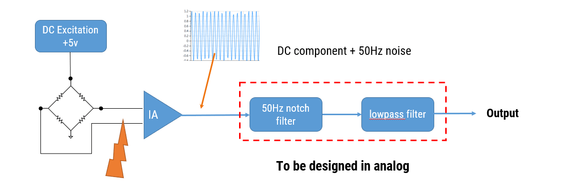
Looking at the hardware setup, we see that have a loadcell excited by a DC excitation voltage, and the general idea is that the sensor’s differential bridge voltage is amplifier by the instrumentation amplifier (IA) when strain is applied.
For those of you unfamiliar with this type of technology, a loadcell is a strain measurement sensor that is comprised of 4 strain gauges, it’s also referred to as a Wheatstone bridge, hence the terminology bridge sensor.
Analysing the signals in the schematic, we see that the differential voltage is passed through 2 filters in order to remove powerline interference and reduce measurement noise.
What are the challenges?
The Instrumentation amplifier (IA) has high impedance inputs, which makes it easy to connect EMI (electromagnet interference) filters to the inputs. However, any mismatches with these filters will generally degrade the instrumentation amplifier’s common-mode rejection ratio, which is undesirable.
The instrumentation amplifier usually has a large gain (100 is quite typical), so any unwanted differential voltage on the inputs will be amplified. Looking at the filters, the notch depth of the powerline cancellation (50Hz/60Hz) filter will be dependent on component tolerances, and will vary over time and with temperature…This is problematic as we’ll discuss in the following section.
Finally, any analog filter or filters will require careful PCB layout and eat up precious board space, which is undesirable for many modern devices.
Loadcell digital – is digital any better ?
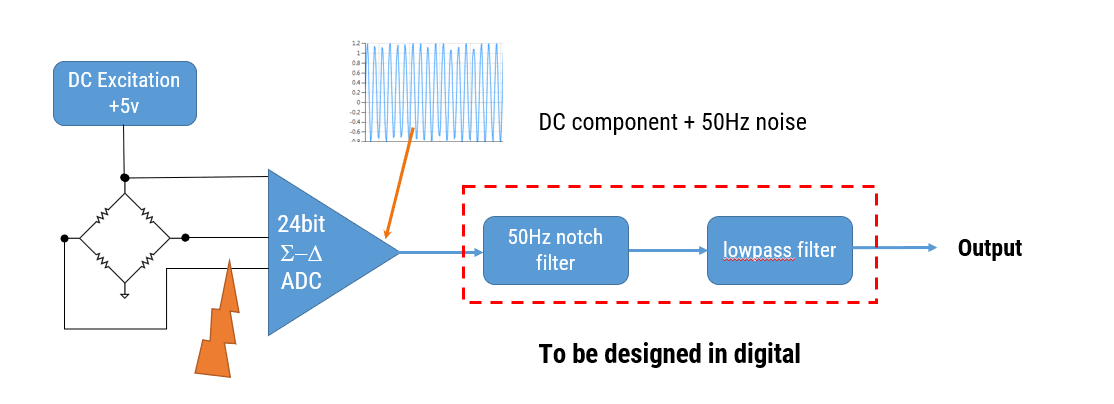
Replacing the instrumentation amplifier with a 24bit sigma-delta ADC (analog-to-digital converter), we simplify the circuitry – although many ADCs don’t tolerate high impedance at their inputs, which may be problematic for good RFI (radio frequency interference) filter design.
Nevertheless, some sigma-delta devices have an in-built 50/60Hz notch filter which simplifies the filtering requirement. Although these devices are more expensive, and the choice of sampling frequency is limited, they may be good enough for some applications.
ASP vs DSP
So, which domain is best for solving our measurement challenge, i.e. do we use analog signal processing (ASP) or digital signal processing (DSP)? In order to answer this objectively, we need to first breakdown the pros and cons of each domain.
Analog filters
Let’s first look at an implementation using ASP.
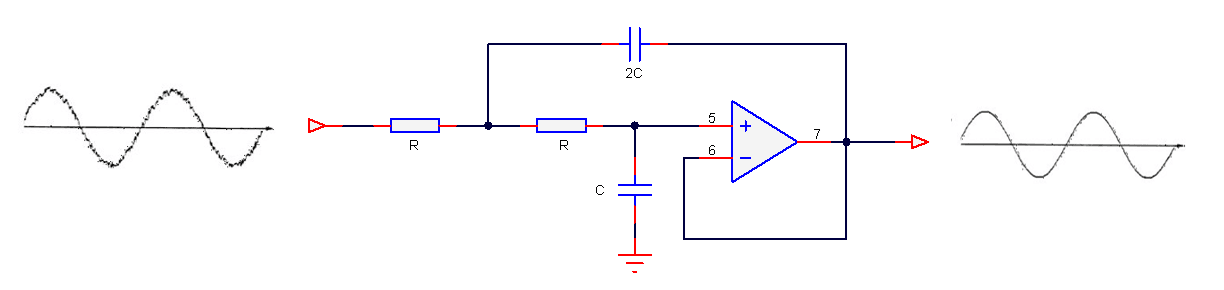
The most obvious advantage is that analog filters have excellent resolution, as there are no ‘number of bits’ to consider. Analog filters have good EMC properties as there is no clock generating noise. There are no effects of aliasing, which is certainly true for the simpler op-amps, which don’t have any fancy chopping or auto-calibration circuitry built into them, and analog designs can be cheap which is great for cost sensitive applications.
Sounds great, but what’s the bad news?
Analog filters have several significant disadvantages that affect filter performance, such as component aging, temperature drift and component tolerance. Also, good performance requires good analog design skills and good PCB layout, which is hard to find in the contemporary skills market.
One big minus point is that filter’s frequency response remains fixed, i.e. a Butterworth filter will always be a Butterworth filter – any changes the frequency response would require physically changing components on the PCB – not ideal!
Digital filters
Let’s now look at an implementation using DSP.
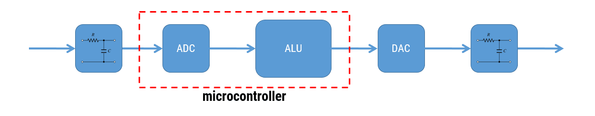
The first impression is that a digital solution is more complicated, as seen above with the five building blocks. However, digital filters have high repeatability of characteristics, and as an example, let’s say that you want to manufacture 1000 measurement modules after optimising your filter design. With a digital solution you can be sure that the performance of your filter will be identical in all modules. This is certainly not the case with analog, as component tolerance, component aging and temperature drift mean that each module’s filter will have its own characteristics.
Digital filters are adaptive and flexible, we can design and implement a filter with any frequency response that we want, deploy it and then update the filter coefficients without changing anything on the PCB!
It’s also easy to design filters with linear phase and at very low sampling frequencies – two things that are tricky with analog.
Sounds great, but what’s the bad news?
The effect of aliasing and if designing in fixed point, finite word length issues must be taken into account, including the limitation of the ADC and DAC. As there is clock source, digital designs will produce more EMI than analog filters. This is potentially the biggest disadvantage of all digital designs if not addressed correctly, and where analog can shine. For example, ADCs will produce more noise at higher sampling rates, which will affect the ADC’s ENOB (effective number of bits) figure. Care should be taken to ensure that as much digital noise is minimised as possible.
Conclusion
When designing modern IoT sensor measurement applications, digital filters offer a greater degree of design flexibility and high repeatability of characteristics over their analog counterparts.
With the advent of modern processor technology and design tooling, it is estimated that about 80% of IoT smart sensor devices are currently deployed using digital devices, such as Arm’s Cortex-M family. The Arm Cortex-M4 is a very popular choice with hundreds of silicon vendors, as it offers DSP functionality traditionally found in more expensive DSPs. Implementation is further simplified by virtue of ASN’s strong partnership with Arm who together provide a rich offering of easy to use filter design tooling and a free DSP software framework (CMSIS-DSP). These tools and well documented software framework allow you to get your IoT application up and running within minutes.

