ASN Filter Designer v5 with easy-to-use code generators to C, Python and C#, for fast and efficient application development. Hardware agnostic.
ASN Filter Designer’s new ANSI C SDK framework, provides developers with a comprehensive automatic C code generator for microcontrollers and embedded platforms. This allows developers to directly deploy their AIoT filtering application from within the tool to any STM32, Arduino, ESP32, PIC32, Beagle Bone and other Arm, RISC-V, MIPS microcontrollers for direct use.
Arm’s CMSIS-DSP library vs. ASN’s C SDK Framework
Thanks to our close collaboration with Arm’s architecture team, our new ultra-compact, highly optimised ANSI C based framework provides outstanding performance compared to other commercial DSP libraries, including Arm’s optimised CMSIS-DSP library.
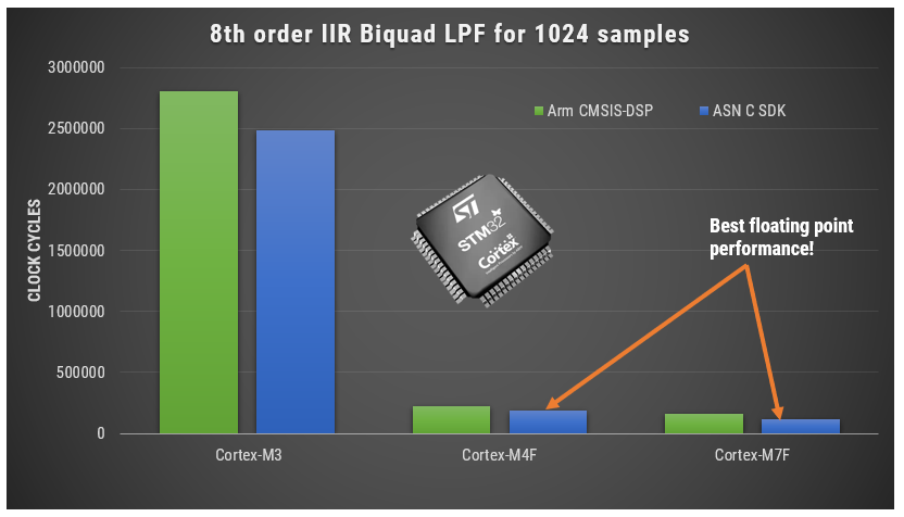
As seen, using o1 complier optimisation, our framework is able to surpass Arm’s CMSIS-DSP library’s performance on an M4F and M7F. Although notice that performance of both libraries is worse on the Cortex-M3, as it doesn’t have an FPU. Despite the difference, both libraries perform equally well, but the ASN DSP library has the added advantage of extra functionality and being platform agnostic, making it ideal for variety of biomedical (ECG, EMG, PPG), audio (sound effects, equalisers) , IoT (temperature, gas, pressure) and I4.0 (flow measurement, vibration analysis, CbM) applications.
AIoT applications designed on the newer Cortex-M33F and Cortex-M55F cores can also take advantage of extra filtering blocks, double precision arithmetic support, providing a simple way of implementing high performance AI on the Edge applications within hours.
Advantages for developers
- A developer can now develop, test and deploy a complete DSP filtering application within the ASN Filter Designer within a few hours. This is very different from a traditional R&D approach that assigns a team of developers for several days in order to achieve the same level of accuracy required for the application.
- Open source and agnostic code base: In order to allow developers to get the maximum performance for their applications, the ASN-DSP SDK is provided as open source and is written in ANSI C. This means that any embedded processor and any level of compiler optimisation can be used.
- Memory size required for the ASN-DSP SDK is relativity lower than other standard DSP libraries, which makes the ASN-DSP SDK extremely suitable for microcontrollers that have memory constrains.
- Using the ASN Filter Designer’s signal analyser tool, developers now can test the performance, accuracy and assess the frequency response of their designed filter and get optimised C code which they can directly use in their application.
- The SDK also supports some extra filtering functions, such as: a median filter, a moving average filter, all-pass, single section IIR filters, a TKEO biomedical filter, and various non-linear functions, including RMS, Abs, Log and Sqrt. These functions form the filter cascade within the tool, and can be used to build signal processing applications, such as EMG and ECG biomedical applications.
- The ASN-DSP SDK supports both single and double precision floating point arithmetic, providing excellent numerical accuracy and wide dynamic range. The library is unique in the sense that it supports double precision arithmetic, which although is not the most optimal for microcontrollers, allows for the implementation of high-fidelity filtering applications.
The ANSI C SDK framework is further extended by our new C# .NET framework, allowing .NET developers to build high performance desktop applications with signal processing capabilities.
Find out more and try it yourself
Benchmarks on a variety of 32-bit embedded platforms, including a biomedical EMG filtering example, are covered in the following application note.
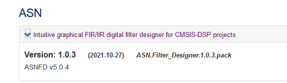
The both framework SDKs are available in ASNFD v5.0, which may be downloaded here.
Drones are one of the golden nuggets in AIoT. No wonder, they can play a pivotal role in congested cities and faraway areas for delivery. Further, they can be a great help to give an overview of a large area or for places which are difficult or dangerous to reach. Advanced Solutions did some research how the companies producing drones has solved some questions regarding their sensor technology. And in drones, there are a lot of sensors- and especial the DC motor control. We found out that with ASN Filter Designer, producers could have saved time and energy in the design of their algorithms with ASN Filter Designer.
Until now: hard-by found solutions
We found out that most producers had come very hard-by to their solutions. And that, when solutions are found, they are far from near perfect.
Probably, this producer has spent weeks or even months on finding these solutions. With ASN Filter Designer, he could have come to a solution within days or maybe hours. Besides, we expect that the measurement would be better too.
The most important issue is that algorithms were developed by handwork: developed in a ‘lab’ environment and then tried in real-life. With the result of the test, the algorithm would be adjusted again. Because a ‘lab’ environment where testing circumstances are stable, it’s very hard work to make the models work in ‘real’ life. For this, rounds and rounds of ‘lab development’ and ‘real life testing’ have to be made.
How ASN Filter Designer could have saved a lot of time and energy
ASN Filter Designer could have saved a lot of time in the design of the algorithms the following ways:
- Design, analyze and implement filters for Drone senor applications
- Filters for speed and positioning control using sensorless BLDC motors
- Speed up deployment
Real-time feedback and powerful signal analyzer
One of the key benefits of the ASN Filter Designer and signal analyzer is that it gives real-time feedback. Once an algorithm is developed, it can easily be tested on real-life data. To capture the real-life data, the ASN Filter Designer has a powerful signal analyzer in place. The tool’s signal analyzer implements a robust zero-crossings detector, allowing engineers to evaluate and fine-tune a complete sensorless BLDC control algorithm quickly and simply.
Design and analyze filters the easy way
You can easily design, analyze and implement filters for drone sensor applications. Including: loadcells, strain gauges, torque, pressure, temperature, vibration and ultrasonic sensors. And assess their dynamic performance in real-time with different input conditions. With the ASN Filter Designer, no algorithms are needed: you just have to drag the filter design. The tool calculates the coordinates itself.
For speed and position control using sensorless BLDC (brushless DC) motors based on back-EMF filtering you can easily experiment with the ASN Filter Designer. See the results in real-time for various IIR, FIR and median (majority filtering) digital filtering schemes. The tool’s signal analyzer implements a robust zero-crossings detector. So you can evaluate and fine-tune a complete sensorless BLDC control algorithm quickly and simply.
Speed up deployment
Perform detailed time/frequency analysis on captured test datasets and fine-tune your design. Our Arm CMSIS-DSP and C/C++ code generators and software frameworks speed up deployment to a DSP, FPGA or micro-controller.
Drones use lots of sensors, and most challenges will be solved with them! ASN Filter Designer provides you with a simple way of improving your sensor measurement performance with its interactive design interface.
So, if you have a measurement problem, ask yourself: will I have a lot of frustrating and costs (maybe not ‘out of pocket’, but still: costs) of creating a filter by hand? Or would I create my filter within days or even hours and save a lot of headache and money. Because: it’s already possible to have a full 3-month license for only 140 euro!

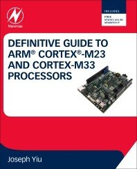
New book on Arm’s latest processors: The Definitive Guide to Arm Cortex-M23 and Cortex-M33 Processors. The book is written by Joseph Yiu, Arm’s resident architecture guru. It features benchmarks and experiments with our DSP filter design tooling (ASN Filter Designer) using CMSIS-DSP for Arm’s latest processors
We’re proud that Dr. Sanjeev Sarpal, Director of AI at Advanced Solutions Nederland has provided support in the digital filter design topic. We’re also very pleased to announce that Joseph Yiu’s new book features a chapter on the ASN Filter Designer for AI/IoT applications using the M23 and M33 Cortex-M cores. Advanced Solutions Nederland works closely with Arm’s DSP/architecture team for AI/DSP solutions using their cores. We’re currently working with Arm on releasing whitepapers on the Cortex-M55.
Armv8-M architecture and its features
The Definitive Guide to Arm® Cortex®-M23 and Cortex-M33 Processors focuses on the Armv8-M architecture and the features that are available in the Cortex-M23 and Cortex- M33 processors.
This book covers a range of topics, including:
- the instruction set
- the programmer’s model
- interrupt handling
- OS support
- debug features
It demonstrates how to create software for the Cortex-M23 and Cortex-M33 processors by way of a range of examples. This enables embedded software developers to understand the Armv8-M architecture.
Worked out examples with ASN Filter Designer
Joseph Yiu’s new book features a chapter on the ASN Filter Designer for AI/IoT applications using the M23 and M33 Cortex-M cores. Our Director of AI, Dr. Sanjeev Sarpal, has provided support.
“The ASN Filter Designer Professional software supports a wide range of filter types. Its design allows filters to be designed via an interactive user interface, where various parameters can be adjusted and the design’s output can immediately be viewed. It also supports the simulation of the filter’s response so that the simulation outputs can be examined to determine whether the filter meets the requirements of the application. An added bonus, for developers creating software for Cortex-M processors, is that it generates C code that directly call CMSIS-DSP library functions (the designed filters can also be exported to C/C++, Python, Matlab, etc.).”
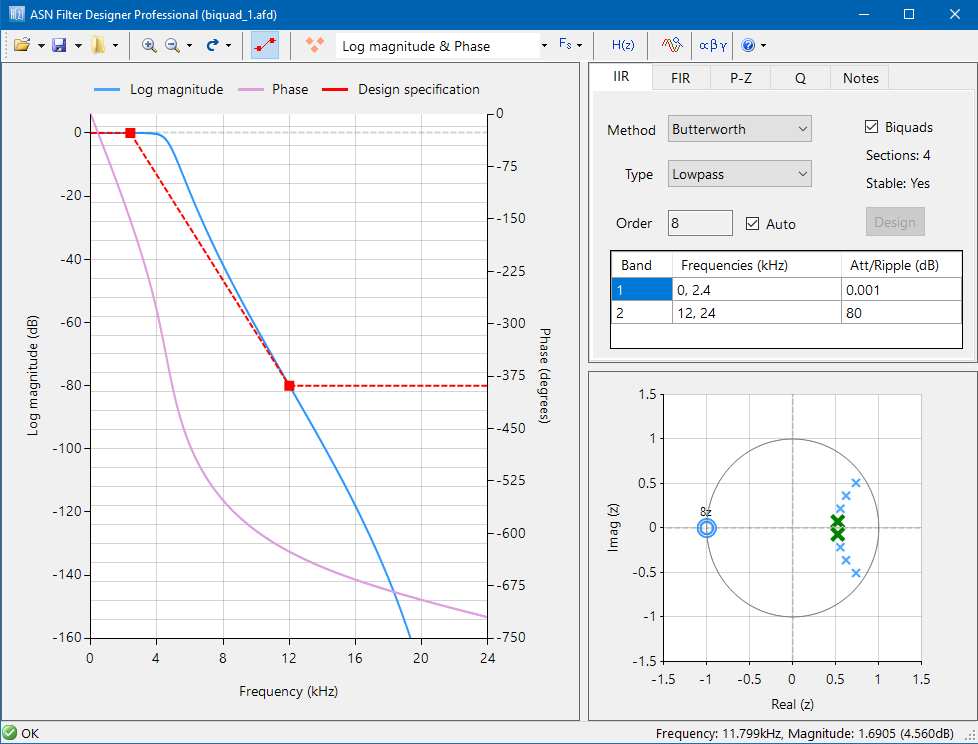
“A number of commercial filter-design software tools are designed specifically for filter-design tasks and make it easier tot analyze a filters’ characteristics. For software developers who are not familiar with filter designs, these tools can be a great help” (p. 820). Thereby, Joseph Yiu uses the ASN Filter Designer for worked out examples. He creates a low pass biquad filter for a system with 48kHz sampling rate and with single-precision floating-point data type.
Order your copy here
DSP for engineers: the ASN Filter Designer is the ideal tool to analyze and filter the sensor data quickly. Create an algorithm within hours instead of days. When you are working with sensor data, you probably recognize these challenges:
- My sensor data signals are too weak to even make an analysis. So, strengthening of the signals is needed
- Where I would expect a flat line, the data looks like a mess because of interference and other containments. I need to clean the data first before analysis
Until now, you’ve probably spent days or even weeks working on your signal analysis and filtering? The development trajectory is generally slow and very painful.
In fact, just think about the number of hours that you could have saved if you had design tool that managed all of the algorithmic details for you. ASN Filter Designer is an industry standard solution used by thousands of professional developers worldwide working on IoT projects.
Our close collaboration with Arm and ST ensures that all designed filters are 100% compatible with all Arm Cortex-M processors, such as ST’s popular STM32 family.
Challenges for engineers
- 90% of IoT smart sensors are based on Arm Cortex-M processor technology
- Sensor signal processing is difficult
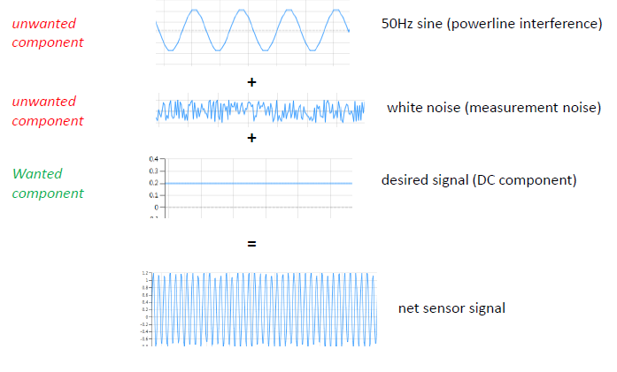
- Sensors have trouble with all kinds of interference and undesirable components
- How do I design a filter that meets my requirements?
- How can I verify my designed filter on test data?
- Clean sensor data is required for better product performance
- Time consuming process to implement a filter on an embedded processor
- Time is money!
Designers hit a ‘brick wall’ with traditional tooling. Standard tooling requires an iterative, trial and error approach or expert knowledge. Using this approach, a considerable amount of valuable engineering time is wasted. ASN Filter Designer helps you with an interactive method of design, whereby the tool automatically enters the technical specifications based on the graphical user requirements.
Fast DSP algorithm development
- Fully validated filter design: suitable for deployment in DSP, micro-controller, FPGA, ASIC or PC application.
- Automatic detailed design documentation: expediting peer review and lowing project risks by helping the designer create a paper trail.
- Simple handover: project file, documentation and test results provide a painless route for handover to colleagues or other teams.
- Easily accommodate other scenarios in the future: Design may be simply modified in the future to accommodate other requirements and scenarios, such as 60Hz powerline interference cancellation, instead of the European 50Hz.
ASN Filter Designer: the fast and intuitive filter designer
The ASN Filter Designer is the ideal tool to analyze and filter the sensor data quickly. When needed, you can easily deploy your data for further analyze for tools such as Matlab and Python. As such it’s ideal for engineers who need and powerful signal analyser and need to create a data filter for their IoT application. Certainly, when you have to create data filtering once in a while. Compared to other tools, you can create an algorithm within hours instead of days.
Easily deploy your algorithms to Matlab, Python, C++ and Arm
A big timesaver of the ASN Filter Designer is that you can easily deploy your algorithms to Matlab, Python, C++ or directly on an Arm microcontroller with the automatic code generators.
Instant pain relief
Just think about the number of hours that you could have saved if you had design tool that managed all of the algorithmic details for you.
ASN Filter Designer is an industry standard solution used by thousands of professional developers worldwide working on IoT projects. Our close collaboration with Arm and ST ensures that the all filters are 100% compatible with all Arm Cortex-M processors.
How much pain relief can 125 Euro buy you?
Because a lot of engineers need our ASN Filter Designer for a short time, a 125 Euro license for just 3 months is possible!
Just ask yourself: is 125 Euro a fair price to pay for instant pain relief and results? We think so. Besides, we have a license for 1 year and even a perpetual license. Download the demo to see for yourself or contact us for more information.

Advanced Solutions Nederland is happy to announce that the ASNFD filtering Arm MDK5 software pack now avalailable for download! The filtering pack provides MDK users with an easy way of ASN’s IP.
Keil MDK is the most comprehensive software development solution for Arm-based microcontrollers. For MDK, additional software components and support for microcontroller devices is provided by software packs. Download here

UI experience 2020 pack
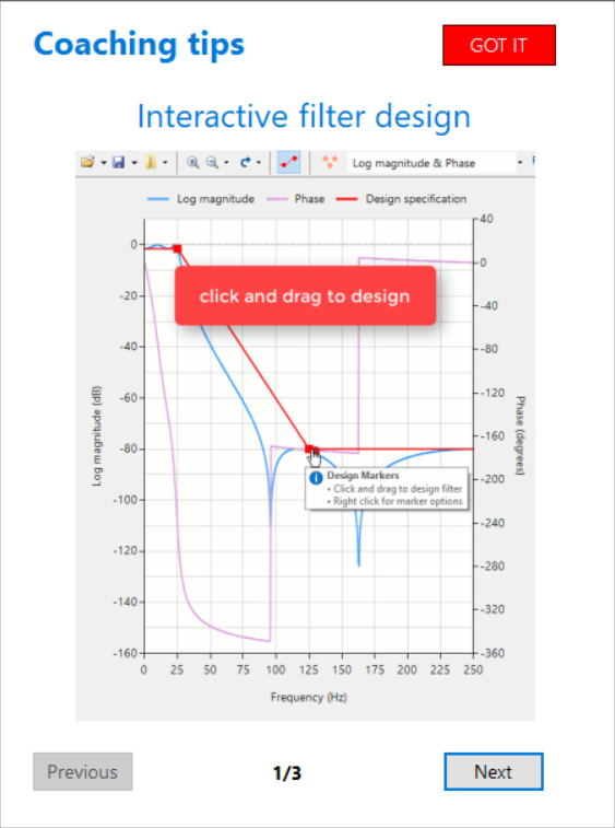
After downloading the ASN Filter Designer, most people just want to play with the tool, in order to get a feeling of whether it works for them. But how do you get started with the ASN Filter Designer? Based on some great user feedback, ASNFD v4.4 now comes with the UI experience 2020 pack. This pack includes detailed coaching tips, an enhanced user experience and step-by-step instructions to get you started with your design.
A quick overview of the ASN Filter Designer v4.4 is given below, and we’re sure that you’ll agree that it’s an awesome tool for DSP IIR/FIR digital filter design!
The ASN Filter Designer has a fast, intuitive user interface. Interactively design, validate and deploy your digital filter within minutes rather than hours. However, getting started with DSP Filter Design can be difficult, especially when you don’t have deep knowledge of digital signal processing. Most people just want to experiment with a tool to get a feeling whether it works for them (sure, there are tutorials and videos). But where do you start?
Start experimenting with filter design immediately
That’s why we have developed the UI Experience 2020 pack. Based on user feedback, we’ve created detailed tooltips and animations of key functionality. Within minutes, you’ll get a kick-start into functionalities such as chart zooming, panning and design markers.
Coaching tips, enhanced user experience, step-by-step instructions
Based on user feedback, the UI Experience 2020 pack includes:
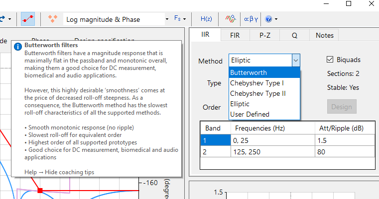
- Extensive coaching tips
- Detailed explanations of design methods and types of filters
- Enhanced user experience:
- cursors
- animations
- visual effects
- Short cuts to detailed worked solutions, tutorials and step-by-step instructions
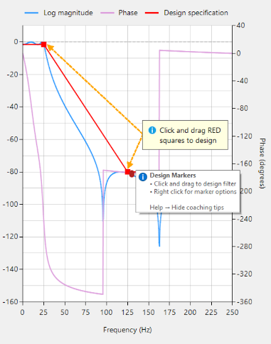
Feedback from the user community has been very positive indeed! By providing detailed tooltips and animations of key functionality, the initial hurdle of designing a filter with your desired specifications has now been significantly simplified.
So start with the ASN Filter Designer right away, and cut your development costs by up to 75%!
Sep 12, 2019. DSP filter design tool ASN filter designer scores top marks in review from embedded software expert, Jacob Beningo
“Digital signal processing (DSP) has become an important tool in the embedded software developer’s toolbox. DSP allows a developer to modify a signal in ways that wouldn’t be otherwise possible. While DSP is often used in audio applications, developers can use DSP to create digital filters that can be used to remove analog hardware from their board as well. An interesting and unique tool for creating digital filters is the ASN Filter Designer and in today’s post, we are going to explore a few of its capabilities.”
Read full review with worked-out example here