Preventive Maintenance is one of the golden nuggets of IOT. How does this focus affect the deployment of personnel?
Efficiencty of personnel: more and better results
Challenge of scarcity of personnel
The challenges of the aging engineer
Efficiency of personnel: more and better results
There was and is a lot of attention what sensors can do for preventive maintenance: with preventive maintenance, huge costs of big repair costs are avoided by acting on time. One aspect in this way of thinking, was that existing personnel could work more efficiently. In old days, mechanics and engineers did their regular scheduled rounds of maintenance, where every device got similar time of attention, whether the device was in a bad state or not. Sensors measure the state of maintenance of devices real-time. As such, personnel can give attention to devices which really needs it. By using your existing personnel in this more efficient way, high personnel costs are saved because no other personnel would have been hired.
Challenge of Scarcity of personnel
When Preventive Maintenance became popular some years ago as one of the fields of Internet of Things, the world was still in the last phase of the economic crisis. Industry has in some ways still crisis thought: yes, personnel is hard to find. But they don’t make the connection that efficiency has changed in the guise of ‘cost saver’ to ‘benefit most from opportunities’. Because personnel is so hard to find, industry has to use the available personnel as efficient and effectively as possible. Besides, engineering for infrastructure isn’t a popular study any longer. So, engineers are even harder to find.
With preventive maintenance with the aid of sensors, personnel can give attention to the devices which really needs them.
The challenges of the aging engineer
There is more: most infrastructure has been built 20 years ago. Already, there’s the challenge that those engineers have moved on to other jobs. So, it’s very possible indeed that in a company, nobody knows how this infrastructure works exactly any longer. Last years, a new challenge has come up: those engineers are beginning to retire. That means that a pool of this specific knowledge is already decreasing and will even lessen more in the years to come. Therefore, it is very important to have measures for maintenance in place, before this knowledge has disappeared completely.
https://www.advsolned.com/wp-content/uploads/2020/06/old-and-young-engineer.jpg390495ASN consultancy teamhttps://www.advsolned.com/wp-content/uploads/2021/07/asn_logo_red_met_tekst_helder-e1755353934770.pngASN consultancy team2020-06-23 11:23:562020-08-13 09:33:00Preventive Maintenance and the challenges of qualified Personnel
The Dutch Newspaper De Gelderlander (June 16) headlines: “Where is the virus, am I safe, am I at risk?” The newspapers write this article in response to the major demonstrations in Amsterdam and Rotterdam two weeks ago. The social distancing measures were not adhered to, as if Covid-19 did not exist. They continue: “Half the country shuddered at the sight of a full Dam. Two weeks later, the coast seems clear. Where are we at risk? Time for a mid-term review. “
The newspaper concludes that there are relatively more infections in South Holland.
Then: “Can we have big events again?” The 2 large demonstrations did not cause a major virus outbreak. That is why many hope that large events can be organized again. “Don’t do it, experts warn … The virus is not yet gone, so such events are big risk moments. The more often you organize those, the more likely it will lead to infections”
Risk situations: frequent mutual contact
Based on various outbreaks, there appears to be 1 major risk situation: places where there is a lot of mutual contact. In addition, the newspaper mentions the outbreak in 2 mosques. Besides, they mention the outbreaks in meat processing and fruit growing. “It is clear that sectors with many migrant workers, who often live close together, are hit harder.” In addition to employees, people who regularly visit these companies were professionals who tested positive, such as drivers.
Finally, the newspaper concludes with the WHO’s warning that places where fruit and meat is traded have risks of major outbreaks. After no new Covid cases were found in China for 2 months, there is currently another outbreak in Beijing.
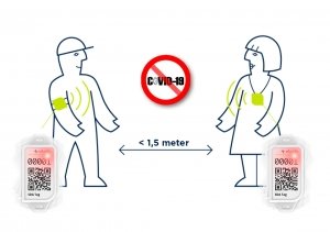
1.5 meters: Social Distancing remains important
Many companies such as offices and factories are currently investigating how they can safely reopen their company for their staff and visitors. Events, cultural institutions and the catering industry also want to offer the safest possible environment. It remains important to keep 1.5 meters away. If you want to learn more how a social distance badge, the covid buzzer can help, visit Covid Buzzer
https://www.advsolned.com/wp-content/uploads/2020/06/social-distancing-covid19-covid-buzzer.jpg5801250ASN consultancy teamhttps://www.advsolned.com/wp-content/uploads/2021/07/asn_logo_red_met_tekst_helder-e1755353934770.pngASN consultancy team2020-06-17 16:02:482020-09-29 10:52:12Frequent mutual contact most important risk situation for Covid-19
A longer lifetime for your equipment with Preventive maintenance
Create the future. Better serve your client, with solutions which weren’t possible until now!
More satisfied customers
More control on your processes
Better Security
One of the most important areas for IoT is Preventive Maintenance. With the modern solutions, you can measure if assets are working properly. And if not, you can repair or replace them, even before those assets have created damage. Examples are:
Are the industrial motors running properly?
Is the oil pressure and quality still ok?
Are there any glitches in the electrical wiring?
How can I save on energy?
With IoT, you can give your equipment a longer lifetime and thus save on repair and replacement costs. Besides, you can spare on costs because you have grip on your processes. For instance: more efficiency on energy costs, better results through optimal deployment of employees
Your customers will become more satisfied with your services. With solutions which weren’t possible until now, products can ‘think’ for their users. In IOT, users raise the expectations and will be dissatisfied with devices which do not help them.
A dashboard helps you to view in one glance which assets are working properly and which are probably in need of repair or replacement. Further, you learn when, where and how intensely your assets are being used, so you use your assets more efficiently.
In a world of connected devices, security is very important. Hackers will try to break in: to steal, to cause harm or to shut down your devices. Without security, hackers can make their entry from anywhere: from one of your devices, but also an unsecured device from one of your employee’s at home. So, in the world of IOT, security of these devices is key.
IoT solutions
IoT solutions prevent accidents from happening and reduce the response time for maintenance. As results, your costs of maintenance will be lower and equipment will have a longer lifetime through Preventive Maintenance.
Sensor measurement solutions look for deviations in normal use. So, you can act upon the first deviations and before the device isn’t working at all. Examples are:
Monitoring the health of an industrial motor
Monitoring oil quality in chain mechanisms
Smart metering for saving energy
Clean sensor data required for sensor fusion and accurate decision making
Sensor data (audio, pressure, temperature, weight, etc.) have to be measured. However, most sensor signals are disturbed by:
Powerline interference and glitches.
Environmental factors (including: dust and other contaminants).
ASN Consultancy is the modern way of working of algorithm design to separate the wanted sensor signals from the undesirable unwanted signals. So, you can analyze and take action on clean and accurate sensor data.
Dashboard
Our tailormade dashboard solutions provide you all the information you need at one glance. So, you act on devices which are not working properly anymore. You can see the use of each device and can even predict the use in time, based on your history data. With this information, you can gain more efficiency or you can improve the satisfaction of your customers.
Security
With a world where everything is connected, security is very important. Because of its importance, its size and the results of an eventual disruption, infrastructure is an important target for terrorist and (future) enemy governments.
Finite impulse response (FIR) filters are useful for a variety of sensor signal processing applications, including audio and biomedical signal processing. Although several practical implementations for the FIR exist, the Direct Form Transposed structure offers the best numerical accuracy for floating point implementation. However, when considering fixed point implementation on a micro-controller, the Direct Form structure is considered to be the best choice by virtue of its large accumulator that accommodates any intermediate overflows.
This application note specifically addresses FIR filter design and implementation on a Cortex-M based microcontroller with the ASN Filter Designer for both floating point and fixed point applications via the Arm CMSIS-DSP software framework. Details are also given (including an Arm reference software pack) regarding implementation of the FIR filter in Arm/Keil’s MDK industry standard Cortex-M micro-controller development kit.
Introduction
ASN Filter Designer provides engineers with a powerful DSP experimentation platform, allowing for the design, experimentation and deployment of complex FIR digital filter designs for a variety of sensor measurement applications. The tool’s advanced functionality, includes a graphical based real-time filter designer, multiple filter blocks, various mathematical I/O blocks, live symbolic math scripting and real-time signal analysis (via a built-in signal analyser). These advantages coupled with automatic documentation and code generation functionality allow engineers to design and validate a digital filter within minutes rather than hours.
The Arm CMSIS-DSP (Cortex Microcontroller Software Interface Standard) software framework is a rich collection of over sixty DSP functions (including various mathematical functions, such as sine and cosine; IIR/FIR filtering functions, complex math functions, and data types) developed by Arm that have been optimised for their range of Cortex-M processor cores.
The framework makes extensive use of highly optimised SIMD (single instruction, multiple data) instructions, that perform multiple identical operations in a single cycle instruction. The SIMD instructions (if supported by the core) coupled together with other optimisations allow engineers to produce highly optimised signal processing applications for Cortex-M based micro-controllers quickly and simply.
ASN Filter Designer fully supports the CMSIS-DSP software framework, by automatically producing optimised C code based on the framework’s DSP functions via its code generation engine.
Designing FIR filters with the ASN Filter Designer
ASN Filter Designer provides engineers with an easy to use, intuitive graphical design development platform for FIR digital filter design. The tool’s real-time design paradigm makes use of graphical design markers, allowing designers to simply draw and modify their magnitude frequency response requirements in real-time while allowing the tool automatically fill in the exact specifications for them.
Consider the design of the following technical specification:
Fs:
500Hz
Passband frequency:
0-25Hz
Type:
Lowpass
Method:
Parks-McClellan
Stopband attenuation @ 125Hz:
≥ 80 dB
Passband ripple:
< 0.01dB
Order:
Small as possible
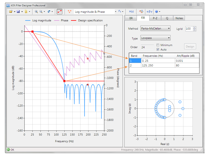
Graphically entering the specifications into the ASN Filter Designer, and fine tuning the design marker positions, the tool automatically designs the filter), automatically choosing the required filter order, and in essence – automatically producing the filter’s exact technical specification!
The frequency response of a filter meeting the specification is shown below:
This Lowpass filter will form the basis of the discussion presented herein.
Parks–McClellan algorithm
The Parks–McClellan algorithm is an iterative algorithm for finding the optimal Chebyshev FIR filter. The algorithm uses an indirect method for finding the optimal filter coefficients, that offers a degree of flexibility over other FIR design methods, in that each band may be individually customised in order to suit the designer’s requirements.
The primary FIR filter designer UI implements the Parks-McClellan algorithm, allowing for the design of the following filter types:
Filter Types
Description
Lowpass
Designs a lowpass filter.
Highpass
Designs a highpass filter.
Bandpass
Designs a bandpass filter.
Bandstop
Designs a bandstop filter.
Multiband
Designs a multiband filter with an arbitrary frequency response.
Hilbert transformer
Designs an all-pass filter with a -90 degree phase shift.
Differentiator
Designs a filter with +20dB/decade slope and +90 degree phase shift.
Double Differentiator
Designs a filter with +40dB/decade slope and a +90 degree phase shift.
Integrator
Designs a filter with -20dB/decade slope and a -90 degree phase shift.
Double Integrator
Designs a filter with -40dB/decade slope and a -90 degree phase shift.
These ten filter types provide designers with a great deal of flexibility for a variety of IoT applications. Design requirements may be simply specified via the use of the design markers. In all cases, the tool will automatically calculate the required filter order to meet the designer’s specification.
The Parks-McClellan algorithm is an optimal Chebyshev FIR design method. However, the algorithm may not converge for some specifications. In such cases, increasing the distance between the design marker bands generally helps.
Other FIR design methods
Designers looking to experiment with other types of FIR design methods may use the ASN FilterScript live symbolic math scripting language. The scripting language supports over 65 scientific commands and provides designers with a familiar and powerful programming language, while at the same time allowing them to implement complex symbolic mathematical expressions. The following functions are supported:
Function
Description
movaver
Moving average FIR filter design.
firwin
FIR filter design based on the Window method.
firarb
Designs an FIR Window based filter with an arbitrary magnitude response.
firkaiser
Designs an FIR filter based on the Kaiser window method.
firgauss
Designs an FIR Gaussian lowpass filter.
savgolay
Design an FIR Savitzky-Golay lowpass smoothing filter.
Please refer to the ASN FilterScript reference guide for more details.
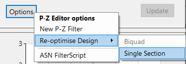
All filters designed in ASN FilterScript are designed using double precision arithmetic in the H2 filter sandbox. An H2 filter must be transformed to an H1 (primary) filter for deployment.
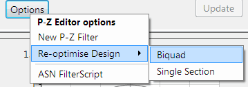
This may be simply achieved via the P-Z options menu:
The re-optimise method automatically analyses and converts the H2 filter into an H1 filter.
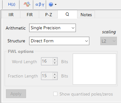
Floating point implementation
When implementing a filter in floating point (i.e. using double or single precision arithmetic) the Direct Form Transposed structure is considered the most numerically accurate. This can be readily seen by analysing the difference equations below (used for implementation), as the undesirable effects of numerical swamping are minimised, since floating point addition is performed on numbers of similar magnitude.
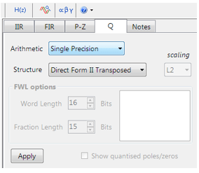
The quantisation and filter structure settings used to implement the FIR can be found under the Q tab (as shown below).
Despite the Direct FormTransposed structure being the most efficient for floating point implementation, the Arm CMSIS-DSP library does not currently support the Direct FormTransposed structure for FIR filters. Only the Direct Form structure is supported.
Setting Arithmetic to Single Precision and Structure to Direct Form and clicking on the Apply button configures the FIR considered herein for the CMSIS-DSP software framework.
The optimised functions within the Arm CMSIS-DSP framework currently support Single Precision arithmetic only.
Support for Double Precision and the Direct FormTransposed structure will be added in future releases.
Fixed point implementation
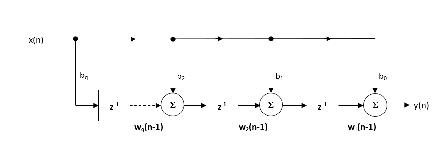
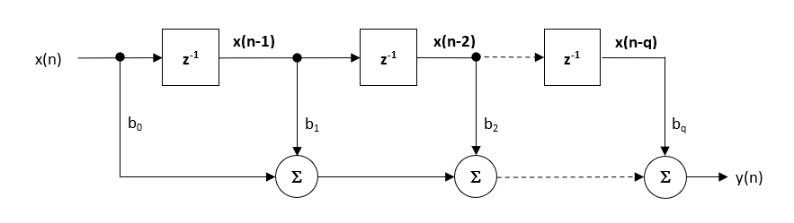
When implementing a filter with fixed point arithmetic, the Direct Form structure is considered to be the best choice by virtue of its large accumulator that accommodates any intermediate overflows. The Direct Form structure and associated difference equation are shown below.
Direct form structure (for fixed point implementation)
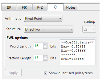
The CMSIS-DSP Framework supports Q7, Q15 and Q31 coefficient quantisation only. The options may be simply specified via the quantisation tab Q as shown below:
The tool’s inbuilt analytics (shown in the textbox) are intended to help the designer choose the most suitable quantisation settings.
As seen on the left, the tool has recommended a RFWL (recommended fraction length) of 15bits (Q15) for the coefficients, which is as required.
The Direct form structure is chosen over the Direct Form Transposed as a single (40-bit) accumulator can be used. The tool’s automatic code generator makes use of CMSIS-DSP’s 64-bit accumulators functions, so that the final C code deployed to a Cortex-M device will not overflow.
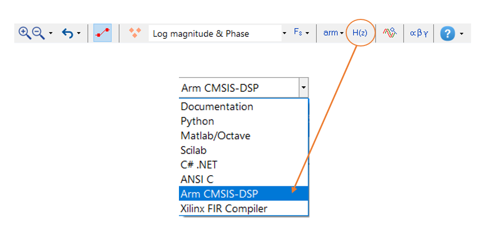
Deploying Arm CMSIS-DSP compliant code
The ASN Filter Designer’s automatic code generation engine facilitates the export of a designed filter to Cortex-M Arm based processors via the Arm CMSIS-DSP software framework. The tool’s built-in analytics and help functions assist the designer in successfully configuring the design for deployment.
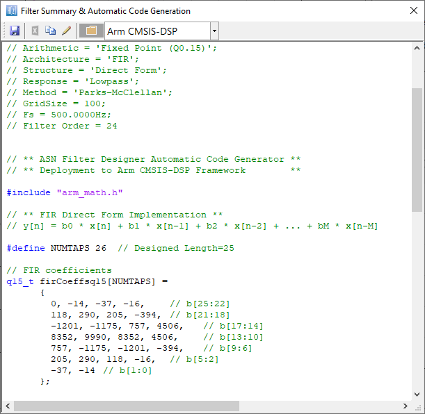
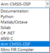
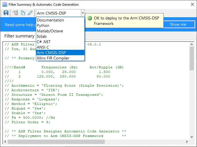
Select the Arm CMSIS-DSP framework from the selection box in the filter summary window:
The automatically generated C code based on the Arm CMSIS-DSP framework for direct implementation on an Arm based Cortex-M processor is shown below:
This code may be directly used in any Cortex-M based development project.
Arm Keil’s MDK (uVision)
As mentioned above, the code generated by the Arm CMSIS DSP code generator may be directly used in any Cortex-M based development project tooling, such as Arm Keil’s industry standard uVision MDK (micro-controller development kit).
The following Arm software pack is available on Keil’s website for using this code directly with Keil uVision MDK.
https://www.advsolned.com/wp-content/uploads/2020/04/df2T_fir.png306900ASN consultancy teamhttps://www.advsolned.com/wp-content/uploads/2021/07/asn_logo_red_met_tekst_helder-e1755353934770.pngASN consultancy team2020-06-11 17:36:292022-11-25 14:51:35Implementing FIR filters with the ASN Filter Designer and the Arm CMSIS-DSP software framework
As of 1 June, many museums in the Netherlands have reopened to a limited extent: a maximum of 30 people can enter at the same time and they must be kept at least 1.5 meters apart. From July 1, this capacity will be increased to 100 people, if there are no problems. Under which conditions this will happen is not known. In any case, museums and events will have to ensure that the 1.5 meters is maintained.
Many museums are taking measures to provide visitors and employees with a safe environment. Find out how the Covid Buzzer can help.
Maximum capacity and time slots
The most obvious measure is to limit visitor numbers at the gate: visitors sign up for a time slot. A museum usually calculates the capacity per time slot on the basis of the available space. In any case, until 1 July, 10m2 must be available per visitor. The average duration of a museum visit is then also important: on the basis of its capacity and the average duration, the museum has an indication of the number of time slots required and the mutual overlap of these time slots.
Irregular spread
However, visitors will not be regularly scattered around the building. It is likely to be busy at some parts of the building: at entrances, wardrobes, toilets, museum shops, etc. And the same applies to the absolute top pieces: the pieces that all visitors want to see and want to view for quite some time. Museums have created walking routes and have made capacity planning that takes into account crowds at the ‘hot spots’ and where an extra security guard must be placed.
Self-regulating power and more capacity with the Covid Buzzer
Offering “experience” is an important condition for a successful museum visit. Visitors also want to feel welcome in Covid time. Many visitors will understand that for safety reasons they may be led through 1.5 rows along the top piece with a distance of 1.5 meters. For the rest, they will prefer to design their visit as much as possible themselves.
When visitors are enjoying themselves, they may forget to keep a distance. In addition, there will unfortunately always be visitors who do not want to take other visitors into account at all.
The Covid Buzzer helps visitors keep 1.5 meters social distance. By having every visitor wear a Covid Buzzer, these problems are solved. This goes off when visitors come within a radius of 1.5 meters. The Covid Buzzer can also offer a solution for the masterpieces, by letting visitors ensure that they keep a distance of 1.5 meters. And employees can address those who do not obey the rules several times.
Covid Buzzer: Simple, reliable and no privacy issues
The simple solution to keep a safe distance between each other. Everyone in the office, factory or elsewhere where many people gather, wears a buzzer. As soon as the buzzer meets another buzzer within a radius of 1.5 meters, a warning signal follows. The buzzer is completely anonymous, so there are no privacy issues involved. Thanks to UWB technology, the Covid buzzer has 10 cm accuracy.
Government rules after July 1; proof for 1.5 meters
As mentioned, the regulations are still unclear after 1 July. Much will depend on the extent to which museums and other visitors attracting institutions appear to be able to comply with the 1.5-meter provisions.
With the Covid Buzzer, museums show that they are actually able to adhere to the 1.5-meter stipulation.
https://www.advsolned.com/wp-content/uploads/2020/06/woman-covid-19-museum-covid-buzzer.jpg5801250ASN consultancy teamhttps://www.advsolned.com/wp-content/uploads/2021/07/asn_logo_red_met_tekst_helder-e1755353934770.pngASN consultancy team2020-06-09 15:50:392020-09-29 10:54:40How to maintain the social distance in a Museum with the Covid Buzzer
Container thefts are increasingly common. “What should you do with such a thing?” headlines the newspaper article. Recently, the police found a number of containers that were once stolen. Tracy, the IOT track and trace device, can help you.
Why should someone want to steal a container?
So, why should someone want to steal a container? For an outsider, it might sound a bit strange. Customers see the container mostly as a kind of large, metal ‘box’ to dispose waste. For a container company, the hiring of the container means trust in your logistic solutions. But for a thief, a container means an easy to steal loot: it’s already packed and stands ready to pick-up!
Stealing is that simple: the scrap metal booty is already packed!
Stealing containers with scrap metal is especially popular. That does not have to mean that a container actually contains scrap metal or is completely full: the thief’s hope for loot is enough. Stealing a container is pretty simple: all the thief needs is a truck. He can put the container on the back with a cable or grab arm in no time. This theft means a major loss for companies: a container can easily cost 5 to 10 thousand euros, beside the eventual value of the cargo. And possibly the trust the customer has in you.
All that most companies do untill now is to share on social media camera images of their container or the truck that was stolen. Hoping to find the thief. Or at least to prevent a recurrence.
Tracy IoT helps: track and trace
• Perimeter detection
• Track and trace on container: Immediate theft signal
Perimeter detection
Tracy checks whether persons enter the site. When “strange” people enter the site, a signal is immediately triggered. Besides, Tracy monitors the movement of people and assets within the perimeter. Tracy uses Ultra Wide Band (UWB). One of the big advantages of UWB is its accuracy, so you know immediately where to look.
Track and trace on container: Immediate theft signal
When there are movements around a container, a signal goes off. If these are “strange”, for example at late times when nobody should be present, you can take immediate action. If the container is taken along anyway, it can be detected by the UWB signal.
Although the design of FIR filters with linear phase is an easy task. This is certainly not true for IIR filters that usually have a highly non-linear phase response, especially around the filter’s cut-off frequencies. This article discusses the characteristics needed for a digital filter to have linear phase, and how an IIR filter’s passband phase can be modified in order to achieve linear phase using all-pass equalisation filters.
Why do we need linear phase filters?
Digital filters with linear phase have the advantage of delaying all frequency components by the same amount, i.e. they preserve the input signal’s phase relationships. This preservation of phase means that the filtered signal retains the shape of the original input signal. This characteristic is essential for audio applications as the signal shape is paramount for maintaining high fidelity in the filtered audio. Yet another application area that requires this, is ECG biomedical waveform analysis, as any artefacts introduced by the filter may be misinterpreted as heart anomalies.
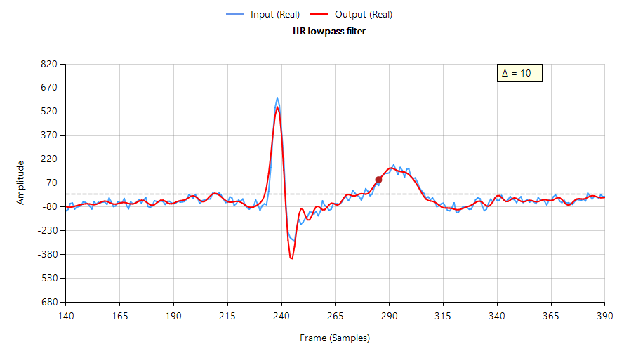
The following plot shows the filtering performance of a Chebyshev type I lowpass IIR on ECG data – input waveform (shown in blue) shifted by 10 samples (\(\small \Delta=10\)) to approximately compensate for the filter’s group delay. Notice that the filtered signal (shown in red) has attenuated, broadened and added oscillations around the ECG peak, which is undesirable.
Figure 1: IIR lowpass filtering result with phase distortion
In order for a digital filter to have linear phase, its impulse response must have conjugate-even or conjugate-odd symmetry about its midpoint. This is readily seen for an FIR filter,
Analysing Eqn. 3, we see that roots (zeros) of \(\small H(z)\) must also be the zeros of \(\small H^\ast (1/z^\ast)\). This means that the roots of \(\small H(z)\) must occur in conjugate reciprocal pairs, i.e. if \(\small z_k\) is a zero of \(\small H(z)\), then \(\small H^\ast (1/z^\ast)\) must also be a zero.
Why IIR filters do not have linear phase
A digital filter is said to be bounded input, bounded output stable, or BIBO stable, if every bounded input gives rise to a bounded output. All IIR filters have either poles or both poles and zeros, and must be BIBO stable, i.e.
Where, \(\small h(k)\) is the filter’s impulse response. Analyzing Eqn. 4, it should be clear that the BIBO stability criterion will only be satisfied if the system’s poles lie inside the unit circle, since the system’s ROC (region of convergence) must include the unit circle. Consequently, it is sufficient to say that a bounded input signal will always produce a bounded output signal if all the poles lie inside the unit circle.
The zeros on the other hand, are not constrained by this requirement, and as a consequence may lie anywhere on z-plane, since they do not directly affect system stability. Therefore, a system stability analysis may be undertaken by firstly calculating the roots of the transfer function (i.e., roots of the numerator and denominator polynomials) and then plotting the corresponding poles and zeros upon the z-plane.
Applying the developed logic to the poles of an IIR filter, we now arrive at a very important conclusion on why IIR filters cannot have linear phase.
A BIBO stable filter must have its poles within the unit circle, and as such in order to get linear phase, an IIR would need conjugate reciprocal poles outside of the unit circle, making it BIBO unstable.
Based upon this statement, it would seem that it’s not possible to design an IIR to have linear phase. However, a discussed below, phase equalisation filters can be used to linearise the passband phase response.
Phase linearisation with all-pass filters
All-pass phase linearisation filters (equalisers) are a well-established method of altering a filter’s phase response while not affecting its magnitude response. A second order (Biquad) all-pass filter is defined as:
Where, \(\small f_c\) is the centre frequency, \(\small r\) is radius of the poles and \(\small f_s\) is the sampling frequency. Notice how the numerator and denominator coefficients are arranged as a mirror image pair of one another. The mirror image property is what gives the all-pass filter its desirable property, namely allowing the designer to alter the phase response while keeping the magnitude response constant or flat over the complete frequency spectrum.
Cascading an APF (all-pass filter) equalisation cascade (comprised of multiple APFs) with an IIR filter, the basic idea is that we only need to linearise the phase response the passband region. The other regions, such as the transition band and stopband may be ignored, as any non-linearities in these regions are of little interest to the overall filtering result.
The challenge
The APF cascade sounds like an ideal compromise for this challenge, but in truth a significant amount of time and very careful fine-tuning of the APF positions is required in order to achieve an acceptable result. Each APF has two variables: \(\small f_c\) and \(\small r\) that need to be optimised, which complicates the solution. This is further complicated by the fact that the more APF stages that are added to the cascade, the higher the overall filter’s group delay (latency) becomes. This latter issue may become problematic for fast real-time closed loop control systems that rely on an IIR’s low latency property.
Nevertheless, despite these challenges, the APF equaliser is a good compromise for linearising an IIRs passband phase characteristics.
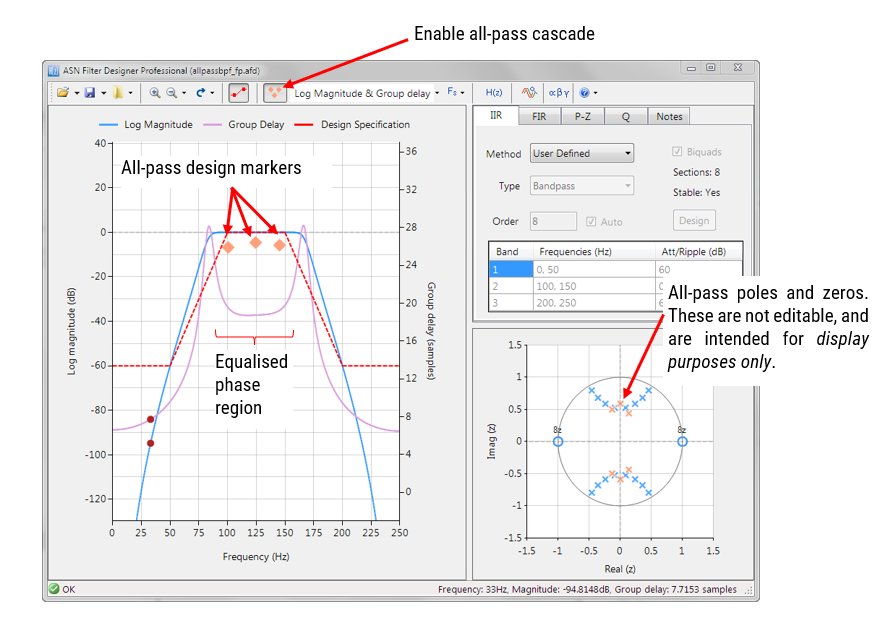
The APF equaliser
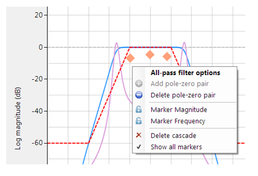
ASN Filter Designer provides designers with a very simple to use graphical all-phase equaliser interface for linearising the passband phase of IIR filters. As seen below, the interface is very intuitive, and allows designers to quickly place and fine-tune APF filters positions with the mouse. The tool automatically calculates \(\small f_c\) and \(\small r\), based on the marker position.
Right clicking on the frequency response chart or on an existing all-pass design marker displays an options menu, as shown on the left.
You may add up to 10 biquads (professional version only).
An IIR with linear passband phase
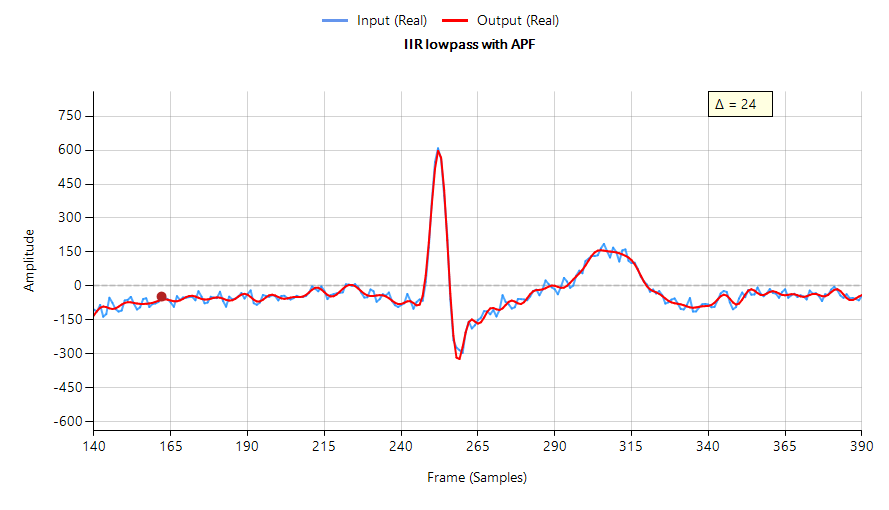
Designing an equaliser composed of three APF pairs, and cascading it with the Chebyshev filter of Figure 1, we obtain a filter waveform that has a much a sharper peak with less attenuation and oscillation than the original IIR – see below. However, this improvement comes at the expense of three extra Biquad filters (the APF cascade) and an increased group delay, which has now risen to 24 samples compared with the original 10 samples.
IIR lowpass filtering result with three APF phase equalisation filters (minimal phase distortion)
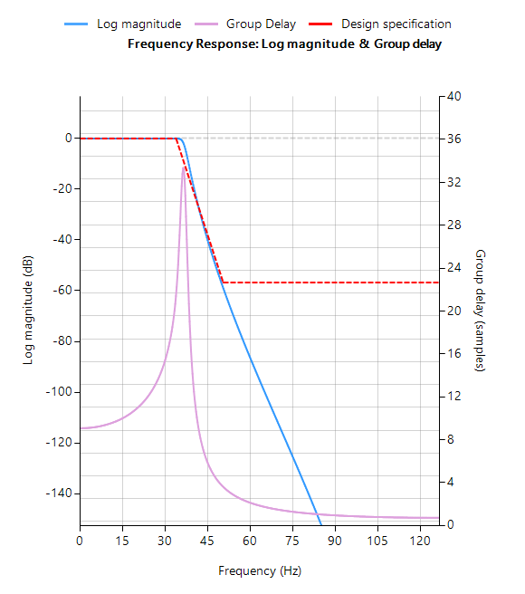
The frequency response of both the original IIR and the equalised IIR are shown below, where the group delay (shown in purple) is the average delay of the filter and is a simpler way of assessing linearity.
IIR without equalisation cascade
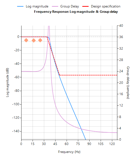
IIR with equalisation cascade
Notice that the group delay of the equalised IIR passband (shown on the right) is almost flat, confirming that the phase is indeed linear.
Automatic code generation to Arm processor cores via CMSIS-DSP
The ASN Filter Designer’s automatic code generation engine facilitates the export of a designed filter to Cortex-M Arm based processors via the CMSIS-DSP software framework. The tool’s built-in analytics and help functions assist the designer in successfully configuring the design for deployment.
Before generating the code, the IIR and equalisation filters (i.e. H1 and Heq filters) need to be firstly re-optimised (merged) to an H1 filter (main filter) structure for deployment. The options menu can be found under the P-Z tab in the main UI.
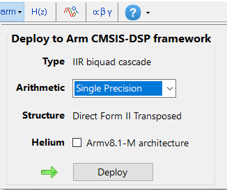
All floating point IIR filters designs should be based on Single Precision arithmetic and either a Direct Form I or Direct Form II Transposed filter structure, as this is supported by a hardware multiplier in the M4F, M7F, M33F and M55F cores. Although you may choose Double Precision, hardware support is only available in some M7F and M55F Helium devices. The Direct Form II Transposed structure is advocated for floating point implementation by virtue of its higher numerically accuracy.
Quantisation and filter structure settings can be found under the Q tab (as shown on the left). Setting Arithmetic to Single Precision and Structure to Direct Form II Transposed and clicking on the Apply button configures the IIR considered herein for the CMSIS-DSP software framework.
Select the Arm CMSIS-DSP framework from the selection box in the filter summary window:
The automatically generated C code based on the CMSIS-DSP framework for direct implementation on an Arm based Cortex-M processor is shown below:
The ASN Filter Designer’s automatic code generator generates all initialisation code, scaling and data structures needed to implement the linearised filter IIR filter via Arm’s CMSIS-DSP library.
Arm deployment wizard
Professional licence users may expedite the deployment by using the Arm deployment wizard. The built in AI will automatically determine the best settings for your design based on the quantisation settings chosen.
The built in AI automatically analyses your complete filter cascade and converts any H2 or Heq filters into an H1 for implementation.
What we have learnt
The roots of a linear phase digital filter must occur in conjugate reciprocal pairs. Although this no problem for an FIR filter, it becomes infeasible for an IIR filter, as poles would need to be both inside and outside of the unit circle, making the filter BIBO unstable.
The passband phase response of an IIR filter may be linearised by using an APF equalisation cascade. The ASN Filter Designer provides designers with everything they need via a very simple to use, graphical all-pass phase equaliser interface, in order to design a suitable APF cascade by just using the mouse!
The linearised IIR filter may be exported via the automatic code generator using Arm’s optimised CMSIS-DSP library functions for deployment on any Cortex-M microcontroller.
Sanjeev is a RTEI (Real-Time Edge Intelligence) visionary and expert in signals and systems with a track record of successfully developing over 26 commercial products. He is a Distinguished Arm Ambassador and advises top international blue chip companies on their AIoT/RTEI solutions and strategies for I5.0, telemedicine, smart healthcare, smart grids and smart buildings.