Notch Filter
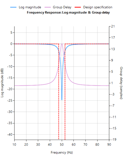
A Notch Filter is also known as a Band Stop filter or Band Reject Filter. The filter passes the signals above and below a specified frequency band unaltered. This band is called the stop band frequency range. And it attenuates (‘rejects’) the frequencies within this range to very low levels.
Syntax
Hd = notch (Fo, BW, DFormat)
Description
IIR notch filter design, defined as:
\(H(z)=\frac{1-2cos w_o z^{-1}+z^{-2}}{1-2rcos w_o z^{-1}+ r^2 z^{-2}}\)
where, \(w_o=\frac{2\pi f_o}{f_s}\) controls the centre frequency, \(f_o\) of the notch, and \( r=1-\frac{\pi BW}{f_s} \)controls the bandwidth (-3dB point) of the notch.
Fo: centre frequency of the notch
BW: Bandwidth (-3dB point) of the notch. Where, \(BW ≤ \frac{F_o}{4}\)
DFormat: allows you to specify the display format of resulting digital filter object.
symbolic |
Display a symbolic representation of the filter object. If the order > 10, the symbolic display option will be overridden and set to numeric |
numeric |
Display a matrix representation of the filter object |
void |
Create a filter object, but do not display output |
Example
[code lang=”java”]ClearH1; // clear primary filter from cascade
ShowH2DM; // show DM on chart
interface BW={5,40,2,10};
Main()
F=75;
Hd=notch(F,BW,”symbolic”);
Num = getnum(Hd); // define numerator coefficients
Den = getden(Hd); // define denominator coefficients
Gain = getgain(Hd); // define gain
[/code]
See also
bessel / butter / cheby1 / cheby2 / ellip / arbmagphase / cplxfreqshift / dcremover / notch / peaking

