FIR Comb Filter: powerline harmonic cancellation and CIC
Comb filters have found use as powerline (50/60Hz) harmonic cancellation filters in audio applications, and form the basis of so called CIC (cascaded integrator–comb) filters used for anti-aliasing in decimation (sample rate reduction), and anti-imaging in interpolation (sample rate increase) applications.
The frequency response of a comb filter consists of a series of regularly-spaced troughs, giving the appearance of a comb. As seen in the plot below, the spacing of each trough appears at either odd or even harmonics of the desired fundamental frequency.
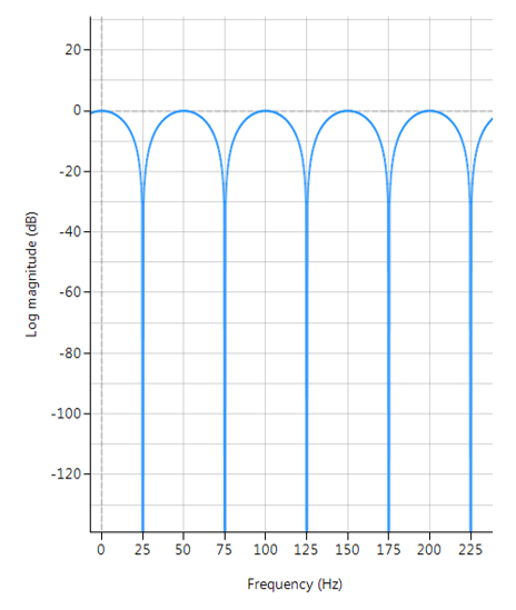 Frequency response of a typical FIR comb filter (odd harmonics cancellation):
\(f_s=500Hz\), \(f_c=25Hz\), \(L=10\) and \(\alpha=1\)
An FIR comb filter can be described by the following transfer function:
\(H(z)=1+\alpha z^{-L}\)
\(\Rightarrow Y(z)=X(z)\left[1+\alpha z^{-L}\right]\)
Clearly, the comb filter is simply a weighted delayed replica of itself, specifiied by \(L\). Taking inverse z-transforms, we obtain the difference equation needed for implementation,
\(y(n)=x(n)+\alpha x(n-L)\)
where, \(\alpha\) is used to set the Q (bandwidth) of the notch and may be either positive or negative depending on what type of frequency response is required. In order to elaborate on this, negative values of \(\alpha\) have their first trough at DC and their second trough at the fundamental frequency. Clearly this type of comb filter can be used to remove any DC components from a measured waveform if so required. All subsequent troughs appear at even harmonics up to and including the Nyquist frequency.
Positive values of \(\alpha\) on the other hand, only have troughs at the fundamental and odd harmonic frequencies, and as such cannot be used to remove any DC components.
Application to powerline interference cancellation
The affectivity of the comb filter is dependent on the sampling frequency, \(f_s\), as \(L\) is limited to integer values only. Also, a relationship between \(f_s\), as \(L\) and will be dependent on the sign of \(\alpha\). Thus, for the purposes of the mains cancellation application considered in this discussion, only positive values of will be considered, as we need only cancel odd harmonics.
A simple relationship for determining \(L\) can be summarized for positive values of \(\alpha\) as follows:
\(L=ceil\left( \large{\frac{f_s}{2f_c}}\right)\)
where, \(f_c\) is the desired centre point of the fundamental notch frequency. Based on this expression, we can re-calculate the sampling frequency, such that \(f_c\) is a true multiple of \(f_s\)
\(f_{snew}=2f_c L\)
Example of a comb filter
For the example considered herein, i.e. \(f_s=500Hz\) and \(f_c=25Hz\), we obtain \(L=10\). However, if \(f_c=60Hz\), we would need \(L=5\), and a new sampling rate of \(600Hz\) respectively, although it’s interesting to note that \(f_s=480Hz\) for \(L=4\) would also suffice.
Implementation
An FIR comb filter may be implemented in ASN FilterScript as follows:
[code language=”java”]
ClearH1; // clear primary filter from cascade
interface L = {4,20,1,5}; // delay
interface alpha = {-1,1,0.01,1};
Main()
Num = {1,zeros(L-1),alpha}; // numerator coefficients
Den = {1};
Gain = 1/sum(abs(Num));
[/code]


