Infinite impulse response (IIR) filters are useful for a variety of sensor measurement applications, including measurement noise removal and unwanted component cancellation, such as powerline interference. Although several practical implementations for the IIR exist, the Direct form II Transposed structure offers the best numerical accuracy for floating point implementation. However, when considering fixed point implementation on a microcontroller, the Direct Form I structure is considered to be the best choice by virtue of its large accumulator that accommodates any intermediate overflows. This application note specifically addresses IIR biquad filter design and implementation on a Cortex-M based microcontroller with the ASN Filter Designer for both floating point and fixed point applications via the Arm CMSIS-DSP software framework.
Details are also given (including a reference example project) regarding implementation of the IIR filter in Arm/Keil’s MDK industry standard Cortex-M microcontroller development kit.
Introduction
ASN Filter Designer provides engineers with a powerful DSP experimentation platform, allowing for the design, experimentation and deployment of complex IIR and FIR (finite impulse response) digital filter designs for a variety of sensor measurement applications. The tool’s advanced functionality, includes a graphical based real-time filter designer, multiple filter blocks, various mathematical I/O blocks, live symbolic math scripting and real-time signal analysis (via a built-in signal analyser). These advantages coupled with automatic documentation and code generation functionality allow engineers to design and validate a digital filter within minutes rather than hours.
The Arm CMSIS-DSP (Cortex Microcontroller Software Interface Standard) software framework is a rich collection of over sixty DSP functions (including various mathematical functions, such as sine and cosine; IIR/FIR filtering functions, complex math functions, and data types) developed by Arm that have been optimised for their range of Cortex-M processor cores.

The framework makes extensive use of highly optimised SIMD (single instruction, multiple data) instructions, that perform multiple identical operations in a single cycle instruction. The SIMD instructions (if supported by the core) coupled together with other optimisations allow engineers to produce highly optimised signal processing applications for Cortex-M based micro-controllers quickly and simply.
ASN Filter Designer fully supports the CMSIS-DSP software framework, by automatically producing optimised C code based on the framework’s DSP functions via its code generation engine.
Designing IIR filters with the ASN Filter Designer
ASN Filter Designer provides engineers with an easy to use, intuitive graphical design development platform for both IIR and FIR digital filter design. The tool’s real-time design paradigm makes use of graphical design markers, allowing designers to simply draw and modify their magnitude frequency response requirements in real-time while allowing the tool automatically fill in the exact specifications for them.
Consider the design of the following technical specification:
| Fs: | 500Hz |
| Passband frequency: | 0-40Hz |
| Type: | Lowpass |
| Method: | Elliptic |
| Stopband attenuation @ 125Hz: | ≥ 80 dB |
| Passband ripple: | < 0.1dB |
| Order: | Small as possible |
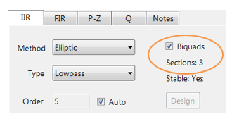
Graphically entering the specifications into the ASN Filter Designer, and fine tuning the design marker positions, the tool automatically designs the filter as a Biquad cascade (this terminology will be discussed in the following sections), automatically choosing the required filter order, and in essence – automatically producing the filter’s exact technical specification!
The frequency response of a 5th order IIR Elliptic Lowpass filter meeting the specifications is shown below:
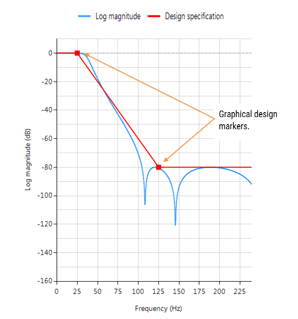
This 5th order Lowpass filter will form the basis of the discussion presented herein.
Biquad IIR filters
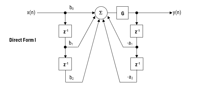
The IIR filter implementation discussed herein is said to be biquad, since it has two poles and two zeros as illustrated below in Figure 1. The biquad implementation is particularly useful for fixed point implementations, as the effects of quantization and numerical stability are minimised. However, the overall success of any biquad implementation is dependent upon the available number precision, which must be sufficient enough in order to ensure that the quantised poles are always inside the unit circle.
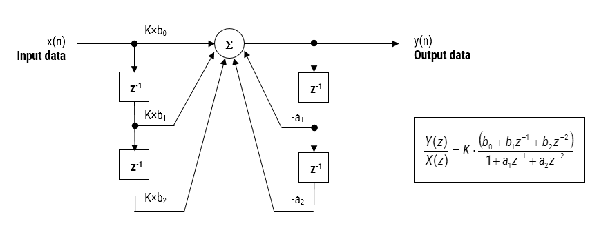
Figure 1: Direct Form I (biquad) IIR filter realization and transfer function.
Analysing Figure 1, it can be seen that the biquad structure is actually comprised of two feedback paths (scaled by \(a_1\) and \(a_2\)), three feed forward paths (scaled by \(b_0, b_1\) and \(b_2\)) and a section gain, \(K\). Thus, the filtering operation of Figure 1 can be summarised by the following simple recursive equation:
\(\displaystyle y(n)=K\times\Big[b_0 x(n) + b_1 x(n-1) + b_2 x(n-2)\Big] – a_1 y(n-1)-a_2 y(n-2)\)
Analysing the equation, notice that the biquad implementation only requires four additions (requiring only one accumulator) and five multiplications, which can be easily accommodated on any Cortex-M microcontroller. The section gain, \(K\) may also be pre-multiplied with the forward path coefficients before implementation.
A collection of Biquad filters is referred to as a Biquad Cascade, as illustrated below.
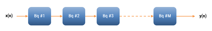
The ASN Filter Designer can design and implement a cascade of up to 50 biquads (Professional edition only).
Floating point implementation
When implementing a filter in floating point (i.e. using double or single precision arithmetic) Direct Form II structures are considered to be a better choice than the Direct Form I structure. The Direct Form II Transposed structure is considered the most numerically accurate for floating point implementation, as the undesirable effects of numerical swamping are minimised as seen by analysing the difference equations.
Figure 2 – Direct Form II Transposed strucutre, transfer function and difference equations
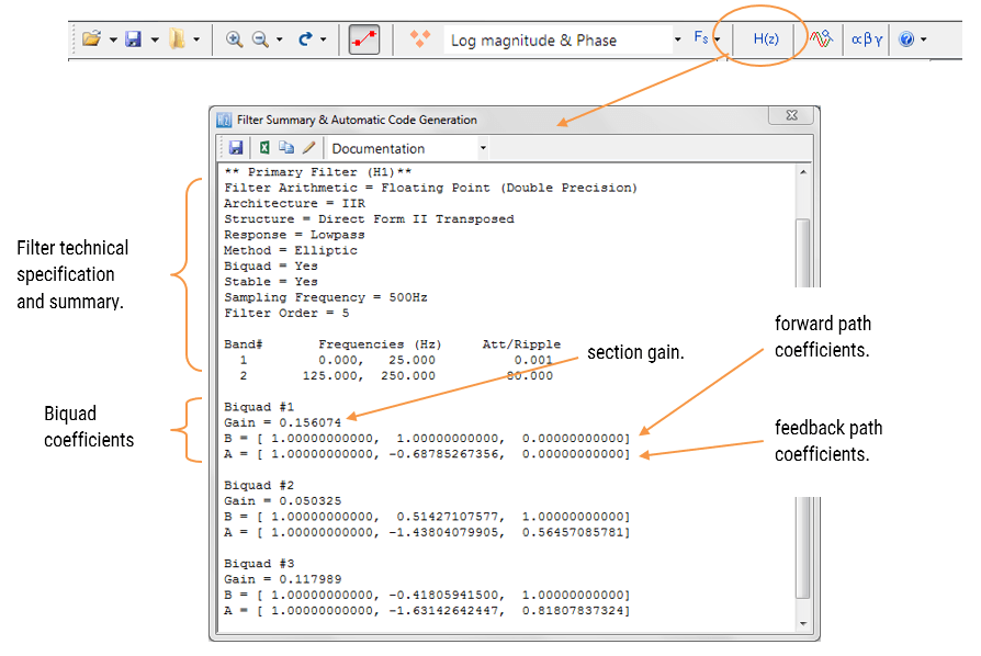
The filter summary (shown in Figure 3) provides the designer with a detailed overview of the designed filter, including a detailed summary of the technical specifications and the filter coefficients, which presents a quick and simple route to documenting your design.
The ASN Filter Designer supports the design and implementation of both single section and Biquad (default setting) IIR filters. However, as the CMSIS-DSP framework does not directly support single section IIR filters, this feature will not be covered in this application note.

The CMSIS-DSP software framework implementation requires sign inversion (i.e. flipping the sign) of the feedback coefficients. In order to accommodate this, the tool’s automatic code generation engine automatically flips the sign of the feedback coefficients as required. In this case, the set of difference equations become,
\(y(n)=b_0 x(n)+w_1 (n-1)\)
\(w_1 (n)= b_1 x(n)+a_1 y(n)+w_2 (n-1)\)
\(w_2 (n)= b_2 x(n)+a_2 y(n)\)
Figure 3: ASN filter designer: filter summary.
Automatic code generation to Arm processor cores via CMSIS-DSP
The ASN Filter Designer’s automatic code generation engine facilitates the export of a designed filter to Cortex-M Arm based processors via the CMSIS-DSP software framework. The tool’s built-in analytics and help functions assist the designer in successfully configuring the design for deployment.
All floating point IIR filters designs should be based on Single Precision arithmetic and either a Direct Form I or Direct Form II Transposed filter structure, as this is supported by a hardware multiplier in the M4F, M7F, M33F and M55F cores. Although you may choose Double Precision, hardware support is only available in some M7F and M55F Helium devices. As discussed in the previous section, the Direct Form II Transposed structure is advocated for floating point implementation by virtue of its higher numerically accuracy.

Quantisation and filter structure settings can be found under the Q tab (as shown on the left). Setting Arithmetic to Single Precision and Structure to Direct Form II Transposed and clicking on the Apply button configures the IIR considered herein for the CMSIS-DSP software framework.
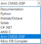
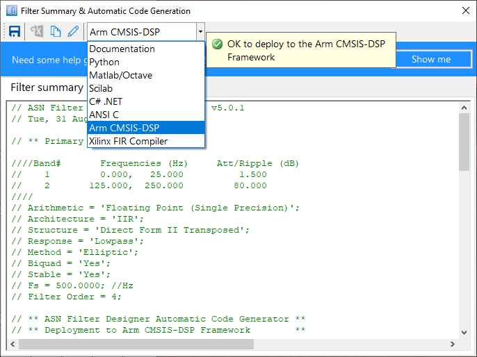
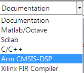
Select the Arm CMSIS-DSP framework from the selection box in the filter summary window:
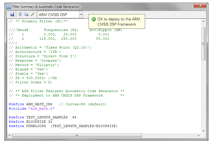
The automatically generated C code based on the CMSIS-DSP framework for direct implementation on an Arm based Cortex-M processor is shown below:
As seen, the automatic code generator generates all initialisation code, scaling and data structures needed to implement the IIR via the CMSIS-DSP library. This code may be directly used in any Cortex-M based development project – a complete Keil MDK example is available on Arm/Keil’s website. Notice that the tool’s code generator produces code for the Cortex-M4 core as default, please refer to the table below for the #define definition required for all supported cores.
ARM_MATH_CM0 | Cortex-M0 core. | ARM_MATH_CM4 | Cortex-M4 core. |
ARM_MATH_CM0PLUS | Cortex-M0+ core. | ARM_MATH_CM7 | Cortex-M7 core. |
ARM_MATH_CM3 | Cortex-M3 core. | ||
ARM_MATH_ARMV8MBL | ARMv8M Baseline target (Cortex-M23 core). | ||
ARM_MATH_ARMV8MML | ARMv8M Mainline target (Cortex-M33 core). |
Automatic code generation of complex coefficient IIR filters is currently not supported (see below for more information).
Arm deployment wizard
Professional licence users may expedite the deployment by using the Arm deployment wizard. The built in AI will automatically determine the best settings for your design based on the quantisation settings chosen.
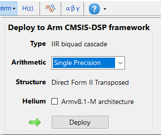
The built in AI automatically analyses your complete filter cascade and converts any H2 or Heq filters into an H1 for implementation. A complex coefficient filter will be automatically converted to real filter for implementation.
Implementing the filter in Arm Keil’s MDK
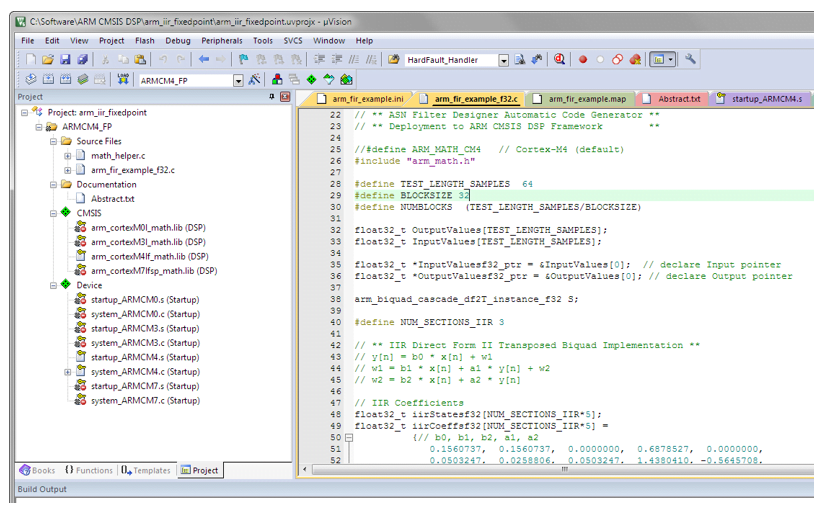
As mentioned in the previous section, the code generated by the Arm CMSIS-DSP code generator may be directly used in any Cortex-M based development project tooling, such as Arm Keil’s industry standard μVision MDK (microcontroller development kit).
A complete μVision example IIR biquad filter project can be downloaded from Keil’s website, and as seen below is as simple as copying and pasting the code and making minor adjustments to the code.
The example project makes use of μVision’s powerful simulation capabilities, allowing for the evaluation of the IIR filter on M0, M3, M4 and M7 cores respectively. As an added bonus, μVision’s logic analyser may also be used, allowing for comparisons between the ASN Filter Designer’s signal analyser and the reality on a Cortex-M core.
Fixed point implementation
As aforementioned, the Direct Form I filter structure is the best choice for fixed point implementation. However, before implementing the difference equation on a fixed point processor, several important data scaling considerations must be taken into account. As the CMSIS-DSP framework only supports Q15 and Q31 data types for IIR filters, the following discussion relates to an implementation on a 16-bit word architecture, i.e. Q15.
Quantisation
In order to correctly represent the coefficients and input/output numbers, the system word length (16-bit for the purposes of this application note) is first split up into its number of integers and fractional components. The general format is given by:
Q Num of Integers.Fraction length
If we assume that all of data values lie within a maximum/minimum range of \(\pm 1\), we can use Q0.15 format to represent all of the numbers respectively. Notice that Q0.15 (or simply Q15) format represents a maximum of \(\displaystyle 1-2^{-15}=0.9999=0x7FFF\) and a minimum of \(-1=0x8000\) (two’s complement format).
The ASN Filter Designer may be configured for Fixed Point Q15 arithmetic by setting the Word length and Fractional length specifications in the Q Tab (see the configuration section for the details). However, one obvious problem that manifests itself for Biquads is the number range of the coefficients. As poles can be placed anywhere inside the unit circle, the resulting polynomial needed for implementation will often be in the range \(\pm 2\), which would require Q14 arithmetic. In order to overcome this issue, all numerator and denominator coefficients are scaled via a biquad Post Scaling Factor as discussed below.
Post Scaling Factor
In order to ensure that coefficients fit within the Word length and Fractional length specifications, all IIR filters include a Post Scaling Factor, which scales the numerator and denominator coefficients accordingly. As a consequence of this scaling, the Post Scaling Factor must be included within the filter structure in order to ensure correct operation.
The Post scaling concept is illustrated below for a Direct Form I biquad implementation.
Figure 4: Direct Form I structure with post scaling.
Pre-multiplying the numerator coefficients with the section gain, \(K\), each coefficient can now be scaled by \(G\), i.e. \(\displaystyle b_0=\frac{b_0}{G}, b_1=\frac{b_1}{G}, a_1=\frac{a_1}{G}, a_2=\frac{a_2}{G}\) and etc. This now results in the following difference equation:
\(\displaystyle y(n)=G \times\Big [b_0 x(n) + b_1 x(n-1) + b_2 x(n-2) – a_1 y(n-1)-a_2 y(n-2)\Big]\)
All IIR structures implemented within the tool include the Post Scaling Factor concept. This scaling is mandatory for implementation via the Arm CMSIS-DSP framework – see the configuration section for more details.
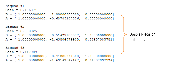
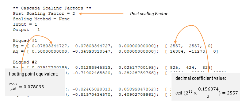
Understanding the filter summary
In order to fully understand the information presented in the ASN Filter Designer filter summary, the following example illustrates the filter coefficients obtained with Double Precision arithmetic and with Fixed Point Q15 quantisation.
Applying Fixed Point Q15 arithmetic (note the effects of quantisation on the coefficient values):
Configuring the ASN Filter Designer for Fixed Point arithmetic
In order to implement an IIR fixed point filter via the CMSIS-DSP framework, all designs must be based on Fixed Point arithmetic (either Q15 or Q31) and the Direct Form I filter structure.
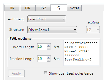
Quantisation and filter structure settings can be found under the Q tab (as shown on the left): Setting Arithmetic to Fixed Point and Structure to Direct Form I and clicking on the Apply button configures the IIR considered herein for the CMSIS-DSP software framework.
The Post Scaling Factor is actually implemented in the CMSIS-DSP software framework as \( \log_2 G\) (i.e. a shift left scaling operation as depicted in Figure 4).
Built in analytics: the tool will automatically analyse the cascade’s filter coefficients and choose an appropriate scaling factor. As seen above, as the largest minimum value is -1.63143, thus, a Post Scaling Factor of 2 is required in order to ‘fit’ all of the coefficients into Q15 arithmetic.
Comparing spectra obtained by different arithmetic rules
In order to improve clarity and overall computation speed, the ASN Filter Designer only displays spectra (i.e. magnitude, phase etc.) based on the current arithmetic rules. This is somewhat different to other tools that display multi-spectra obtained by (for example) Fixed Point and Double Precision arithmetic. For any users wishing to compare spectra you may simply switch between arithmetic settings by changing the Arithmetic method. The designer will then automatically re-compute the filter coefficients using the selected arithmetic rules and the current technical specification. The chart will then be updated using the current zoom settings.
Automatic code generation to the Arm CMSIS-DSP framework
As with floating point arithmetic, select the Arm CMSIS-DSP framework from the selection box in the filter summary window:
The automatically generated C code based on the CMSIS-DSP framework for direct implementation on an Arm based Cortex-M processor is shown below:
As with the floating point filter, the automatic code generator generates all initialisation code, scaling and data structures needed to implement the IIR via the CMSIS-DSP library. This code may be directly used in any Cortex-M based development project – a complete Keil MDK example is available on Arm/Keil’s website. Notice that the tool’s code generator produces code for the Cortex-M4 core as default, please refer to the table below for the #define definition required for all supported cores.
ARM_MATH_CM0 | Cortex-M0 core. | ARM_MATH_CM4 | Cortex-M4 core. |
ARM_MATH_CM0PLUS | Cortex-M0+ core. | ARM_MATH_CM7 | Cortex-M7 core. |
ARM_MATH_CM3 | Cortex-M3 core. | ||
ARM_MATH_ARMV8MBL | ARMv8M Baseline target (Cortex-M23 core). | ||
ARM_MATH_ARMV8MML | ARMv8M Mainline target (Cortex-M33 core). |
The main test loop code (not shown) centres around the arm_biquad_cascade_df2T_f32() function, which performs the filtering operation on a block of input data.
Complex coefficient IIR filters are currently not supported.
Validating the design with the signal analyser
A design may be validated with the signal analyser, where both time and frequency domain plots are supported. A comprehensive signal generator is fully integrated into the signal analyser allowing designers to test their filters with a variety of input signals, such as sine waves, white noise or even external test data.
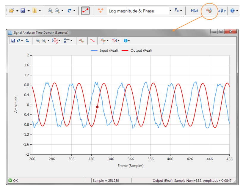
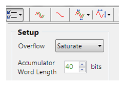
For Fixed Point implementations, the tool allows designers to specify the Overflow arithmetic rules as: Saturate or Wrap. Also, the Accumulator Word Length may be set between 16-40 bits allowing designers to quickly find the optimum settings to suit their application.
Extra resources
- Digital signal processing: principles, algorithms and applications, J.Proakis and D.Manoloakis
- Digital signal processing: a practical approach, E.Ifeachor and B.Jervis.
- Digital filters and signal processing, L.Jackson.
- Step by step video tutorial of designing an IIR and deploying it to Keil MDK uVision.
- Implementing Biquad IIR filters with the ASN Filter Designer and the Arm CMSIS-DSP software framework (ASN-AN025)
- Keil MDK uVision example IIR filter project