Advances in telemedicine healthcare products over the past decades have been truly miraculous with ingenious little devices invented by start-ups as well as by larger corporations, .e.g Apple’s smart watch and the Fitbit. These advancements have been facilitated by the availability of low-cost microcontrollers offering algorithmic functionality, allowing developers to implement wearables with excellent battery life and edge based real-time data analysis.
Over 90% of the microcontrollers used in the smart product market are powered by so called Arm Cortex-M processors that offer a combination of high algorithmic performance, low-power and security. The Arm Cortex-M4 is a very popular choice with hundreds of silicon vendors (including ST, TI, NXP, ADI, Nordic, Microchip, Renesas), as it offers DSP (digital signal processing) functionality traditionally found in more expensive devices and is low-power. Arm and its rich eco system of partners provide developers with easy-to-use tooling and tried and tested software libraries, such as the CMSIS-DSP and CMSIS-NN frameworks for algorithm development and machine learning.
The choice is vast, and can be very confusing. Therefore, here are some practical hints and tips for both managers and developers to help you decide which Arm Cortex-M processor is best for your biomedical product.
Which Arm Cortex-M processor do I choose for my biomedical application?
The Arm Cortex-M0+ processor is an ultra-low power 32-bit processor designed for very low-cost IoT applications, such as simple wearable devices. The low price point is comparable with equivalent 8-bit devices, but with 32-bit performance. Microcontrollers built around the M0+ processor provide developers with excellent battery life (months to years), a rich peripheral set and a basic amount of connectivity and computational performance. The latter means that only simple algorithms can be implemented, such as algorithms for correcting baseline wander and minimizing the effects of motion artefacts using accelerometer data via an adaptive filter, such as the NLMS algorithm. Although for PPG pulse rate measurement applications, the sampling rate is typically 50Hz, leaving the processor plenty of time to perform various simpler algorithmic operations, such as digital filtering and zero-crossing detection.
For high performance PPG applications, sampling rates in the order of 500Hz are typically used. These types of applications usually look at more biomedical features, such as identifying the Systolic and Diastolic phases and finding the Dicrotic notch using feature extraction algorithms and ML models. These extra functionalities provide a significant strain on the processor’s abilities, and as such are beyond the abilities of the M0+.
The Cortex-M3 is a step up from the M0+, offering better computational performance but with less power efficiency. The extra processing power, rich hardware peripheral set for connecting other sensors and connectivity options makes the M3 a very good choice for developers looking to develop slightly more advanced wearable products, such as the Fitbit device that is based on ST’s low-power STM32L series of microcontrollers.
High performance wearables and beyond
The Arm Cortex-M4 processor and its more powerful bigger brother the Cortex-M7 are highly-efficient embedded processors designed for IoT applications that require decent real-time signal processing performance and memory. Depending on the flavour of the processor, the M4F/M7F processors implement DSP hardware accelerated instructions, as well hardware floating point support. This lends itself to the efficient implementation of much more computationally intensive biomedical DSP and ML algorithms needed for more advanced telemedicine products.
The hardware floating point support unit expedites RAD (rapid application development), as algorithms and functions developed in Matlab or Python can be ported to C for implementation without the need for a lengthy data arithmetic quantisation analysis. Microcontrollers based on the M4F or M7F, usually offer many of the hardware peripheral and connectivity advantages of the M3, providing developers with a very powerful, low power development platform for their telemedicine application.
The Arm Cortex-M33 is a step up from the M4 focusing on algorithms and hardware security via Arm’s TrustZone technology and memory-protection units. The Cortex-M33 processor attempts to achieve an optimal blend between real-time algorithmic performance, energy efficiency and system security.
State-of-the art AI microcontrollers
Released in 2020, the Arm Cortex-M55 processor and its bigger brother the Cortex-M85 are targeted for AI applications on microcontrollers. These processors feature Arm’s Helium vector processing technology, bringing energy-efficient digital signal processing (DSP) and machine learning (ML) capabilities to the Cortex-M family. In November 2023, Arm announced the release of Cortex-M52 processor for IoT applications. This processor looks to replace the older M33 processor, as it combines Helium technology with Arm TrustZone technology.
Although the IP for these processors is available for licencing, only a few IC vendors have developed a microcontroller, e.g. Samsung’s Exynos W920 SoC that has been specifically designed for the wearables market. The SoC packs two Arm Cortex-A55 processors, and the Arm Mali-G68 GPU using state-of-the art 5nm semiconductor technology. The chipset also features a dedicated low-power Cortex-M55 display processor for handling AoD (Always-on Display) tasks – although a little over the top for simple wearable devices, the Exynos processor family certainly seems like an excellent choice for building next generation AI capable low-power wearable products.
So, which one do I choose?
The compromise for biomedical product developers when choosing an M4, M7 or M33 based microcontroller over an M3 device usually comes down to a trade-off between algorithmic performance, security requirements and battery life. If good battery life and simple algorithms are key, then M3 devices are a good choice. However, if more computationally intensive analysis algorithms are required (such as ML models), then the M4 or M7 should be used.
As mentioned earlier, the Armv7E-M architecture used in M4/M7 processors supports a DSP extension that implements an SIMD (single instruction, multiple data) architecture extension that can significantly improve the performance of an algorithm. The hardware floating point unit is very good for expediting MAC (multiply and accumulate) operations used in digital filtering, requiring just three cycles to complete. Other DSP operations such as add, subtract, multiply and divide require just one cycle to complete.
The M7 out performs its M4 little brother by offering approximately twice the computational performance and some devices even offer hardware double precision floating point support which make M4/M7 processors attractive for high accuracy algorithms needed for medical analysis.
If data security is paramount, for example protecting and securing transferring patient data to a cloud service, then the M33 or the M52 (when avalaible) are good choices. These devices also offer a high level of protection against tampering and running of authorised code via TrustZone’s trusted execution environment.
Some IC vendors now offer hybrid micro-controllers that implement multi-processors on chip, such as ST’s ST32Wx family that combine the M0+ and M4 in order to get the advantages of each processor and maximise battery life.
Finally, advances in semiconductor technology means that a modern M4F processor produced with 40nm process technology may match or even surpass the energy efficiency of an M3 produced with 90nm technology from several years ago. As such, higher performance processors that were until several years too costly and energy inefficient for low-cost wearables products are rapidly becoming a viable solution to this exciting marketplace.
Sanjeev is a RTEI (Real-Time Edge Intelligence) visionary and expert in signals and systems with a track record of successfully developing over 26 commercial products. He is a Distinguished Arm Ambassador and advises top international blue chip companies on their AIoT/RTEI solutions and strategies for I5.0, telemedicine, smart healthcare, smart grids and smart buildings.
https://www.advsolned.com/wp-content/uploads/2023/04/armcores_biomedical-1.png540865Dr. Sanjeev Sarpalhttps://www.advsolned.com/wp-content/uploads/2021/07/asn_logo_red_met_tekst_helder-e1755353934770.pngDr. Sanjeev Sarpal2023-04-19 10:48:562024-05-25 22:53:36Choosing the right Arm Cortex-M processor for your biomedical smart product: a practical guide
We live in a time where wearable/mobile products comprised of sensors, apps, AI and IoT (AIoT) technology are part of everyday life. Every year we hear about amazing advances in processor technology and AI algorithms for all aspects of life from industrial automation to futuristic biomedical products.
For developers, the requirement to design low-cost products with better battery life, higher computational performance and analytical accuracy, requires access to a suite of affordable processor technology, algorithmic libraries, design tooling and support.
This article aims to provide developers with an overview of all salient points required for algorithm implementation on Arm Cortex-M processors.
Can you give me a concrete example?
Almost all IoT sensor applications require some level of signal processing to enhance data and extract features of interest. This could be temperature, humidity, gas, current, voltage, audio/sound, accelerometer data or even biomedical data.
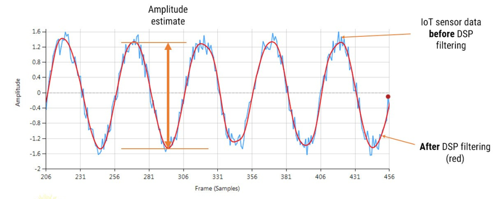
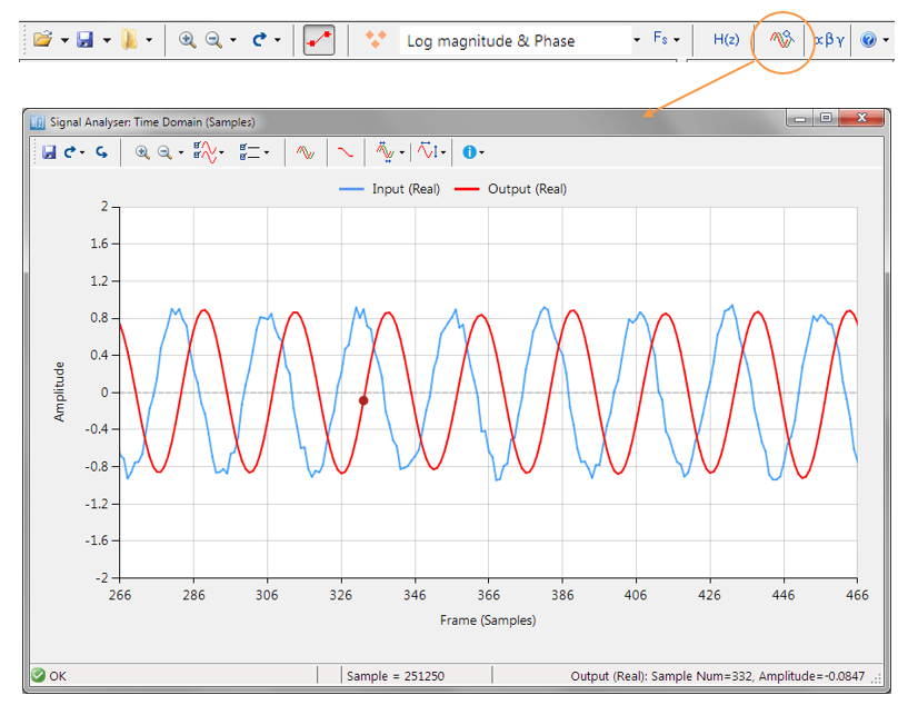
Consider the following application for gas concentration measurement from an Infra-red gas sensor. The requirement is to determine the amplitude of the sinusoid in order to get an estimate of gas concentration – where the bigger amplitude is the higher the gas concentration will be.
Analysing the figure, it can be seen that the sinusoid is corrupted with measurement noise (shown in blue), and any estimate based on the blue signal will have a high degree of uncertainty about it – which is not very useful for getting an accurate reading of gas concentration!
After cleaning the sinusoid with a digital filter (red line), we obtain a much more accurate and usable signal for our gas concentration estimation challenge. But how do we obtain the amplitude?
Knowing that the gradient at the peaks is zero, a relativity easy and robust way of finding the peaks of the sinusoid is via numerical differentiation, i.e. computing the difference between sample values and then looking for the zero-crossing points in the differentiated data. Armed with the positions and amplitudes of the peaks, we can take the average and easily obtain the amplitude and frequency. Notice that any DC offsets and low-frequency baseline wander will be removed via the differentiation operation.
This is just a simple example of how to extract the properties of a sinusoid in real-time using various algorithmic IP blocks. There are of course a number of other methods that may be used, such as complex filters (analytic signals), Kalman filters and the FFT (Fast Fourier Transform).
Arm Cortex-M processor technology
Although a few processor technologies exist for microcontrollers (e.g. RISC-V, Xtensa, MIPS), over 90% of the microcontrollers used in the smart product market are powered by so-called Arm Cortex-M processors that offer a combination of high algorithmic performance, low-power and security. The Arm Cortex-M4 is a very popular choice with several silicon vendors (including ST, TI, NXP, ADI, Nordic, Microchip, Renesas), as it offers DSP (digital signal processing) functionality traditionally found in more expensive devices and is low-power.
Algorithmic libraries and support
An obvious hurdle for many developers is how to port their algorithmic concept or methods from Python/Matlab into embedded C for real-time operation? This is easier said than done, as many software engineers are not well-versed in understanding the mathematical concepts needed to implement algorithms. This is further complicated by the challenge of how to implement algorithms developed by researchers that are not interested/experienced in developing real-time embedded applications.
A possible solution offered by the Mathworks (Embedded Coder) automatically translates Matlab algorithms and functions into C for Arm processors, but its high price tag and steep learning curve make it unattractive for many.
That being said, Arm and its rich ecosystem of partners provide developers with extensive easy-to-use tooling and tried and tested software libraries. Arm’s CMSIS-DSP and CMSIS-NN frameworks for algorithm development and machine learning (ML) are two very popular examples that are open source and are used internationally by tens of thousands of developers.
The Arm CMSIS-DSP software framework is particularly interesting as it provides IoT developers with a rich collection of fast mathematical and vector functions, interpolation functions, digital filtering (FIR/IIR) and adaptive filtering (LMS) functions, motor control functions (e.g. PID controller), complex math functions and supports various data types, including fixed and floating point. The important point to make here is that all of these functions have been optimised for Arm Cortex-M processors, allowing you to focus on your application rather than worrying about optimisation.
The Arm-CMSIS framework solutions are strengthened by Arm partners ASN and Qeexo who provide developers with easy-to-use real-time filtering, feature extraction and ML tooling (AutoML) and reference designs, expediting the development of IoT applications, including industrial, audio and biomedical. These solutions have been optimised for Arm processors with the help of Arm’s architecture experts and insider knowledge of compiler workings.
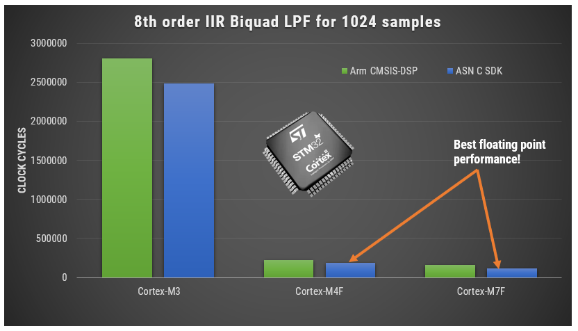
A benchmark of ASN’s floating point application-specific DSP filtering library versus Arm’s CMSIS-DSP library is shown below for three types of Arm cores.
Framework Benchmarks: lower number of clock cycles means higher performance.
As seen, the performance of the ASN library is slightly faster by virtue of the application-specific nature of the implementation. The C code is automatically generated from the ASN Filter Designer tool.
Cortex-M4 and Cortex-M7
The Arm Cortex-M4 processor and its more powerful bigger brother the Cortex-M7 are highly-efficient embedded processors designed for IoT applications that require decent real-time signal processing performance and memory.
Both the Cortex-M4 and M7 core benefit from the Armv7E-M architecture that offers additional DSP extensions. Depending on the flavour of the processor, the M4F/M7F processors implement DSP hardware accelerated instructions (SIMD), as well as hardware floating point support via an FPU (floating point unit), giving them a significant performance boost over the Cortex-M3. The ‘F’ suffix signifies that the device has an FPU.
This lends itself to the efficient implementation of much more computationally intensive DSP and ML algorithms needed for more advanced IoT products and real-time control applications requiring highly deterministic operations.
Microcontrollers based on the M4F or M7F, usually offer many of the hardware peripheral and connectivity advantages of the simpler M3, providing developers with a very powerful, low-power development platform for their IoT application. The Cortex-M7F typically offers much higher performance than its Cortex-M4F little brother, doubling the performance on FFT, digital filters and other critical algorithms.
Floating point or fixed point?
The hardware floating point support unit expedites RAD (rapid application development), as algorithms and functions developed in Matlab or Python can be ported to C for implementation without the need for a lengthy data arithmetic quantisation analysis. Although floating point comes with its own problems, such as numeric swamping, whereby adding a large number to a small number ignores the smaller component. This can become troublesome in digital filtering applications using the standard Direct Form structure. It is for this reason that all floating-point filters should be implemented using the Direct Form Transposed structure, as discussed in the following article.
Correctly designing and implementing these tricks requires specialist knowledge of signal processing and C programming, which may not always be available within an organisation. This becomes even more frustrating when implementing new algorithms and concepts, where the effects of the arithmetic are yet to be determined.
Single vs double precision floating point
For a majority of IoT applications single precision (32-bit) floating point arithmetic will be sufficient, providing approximately 7 significant digits of precision. Double precision (64-bit) floating point provides approximately 15 significant digits of precision, but in truth should only be used in applications that require more than 7 significant digits of precision. Some examples include: FFT based noise cancellation, CIC correction filters and Rogowski coil compensation filters.
Some Cortex-M7F’s (e.g. STM32F769) implement a Double precision FPU providing an extra performance boost to high numerical accuracy IoT applications.
Fixed point
Fixed point is not necessarily less accurate than floating point, but requires much more quantisation analysis, which becomes tricky for signals with a wide dynamic range. As with floating point careful analysis is required, as weird effects can appear due to the level of quantisation used, leading to unreliable behaviour if not properly investigated. It is this challenge that can slow down a development cycle significantly, in some cases taking months to validate a new algorithm.
Many developers have traditionally considered devices without an FPU (e.g., Cortex-M0/M3) as the best choice for low-power battery applications. However, when comparing a modern Cortex-M7 device manufactured using 40nm semiconductor process technology, to that of a ten-year-old Cortex-M3 using 180nm process technology, the Cortex-M7 device will likely have a lower power profile.
Acceleration of DSP calculations
The Armv7E-M architecture supports a DSP extension that implements an SIMD (single instruction, multiple data) architecture extension that can significantly improve the performance of an algorithm. The basic idea behind SIMD involves parallel execution of an instruction (eg. Add, Subtract, Multiply, Divide, Abs etc) on multiple data elements via the use of 64 or 128-bit registers. These DSP extension intrinsics (SIMD optimised instruction) support a variety of data types, such as integers, floating and fixed-point.
The high efficiency of the Arm compiler allows for the automatic dissemination of your C code in order to break it up into SIMD intrinsics, so explicit definition of any DSP extension intrinsics in your code is usually unnecessary. The net result for your application is much faster code, leading to better power consumption and for wearables, better battery life.
What algorithmic operations would use this?
The following examples give an idea of operations that can be significantly speeded up with SIMD intrinsics:
vadd can be used to expedite the calculation of a dataset’s mean. Typical applications include average temperature/humidity readings over a week, or even removing the DC offset from a dataset.
vsub can be used to expedite numerical differentiation in peak finding, as discussed in the example above.
vabs can be used for expediting the calculation of an envelope of a fullwave rectified signal in EMG biomedical and smartgrid applications.
vmul can be used for windowing a frame of data prior to FFT analysis. This is also useful in audio applications using the overlap-and-add method.
The hardware floating point unit is very good for expediting MAC (multiply and accumulate) operations used in digital filtering, requiring just three cycles to complete. Other DSP operations such as add, subtract, multiply and divide require just one cycle to complete.
Combining DSP, low-power and security: The Cortex-M33
The Arm Cortex-M33 is based on the Armv8-M architecture and is a step up from the Cortex-M4 focusing on algorithms and hardware security via Arm’s TrustZone technology and memory-protection units. The Cortex-M33 processor attempts to achieve an optimal blend between real-time algorithmic performance, energy efficiency and system security.
TrustZone technology
Arm TrustZone implements a security paradigm that discriminates between the running and access of untrusted applications running in a Rich Execution Environment (REE) and trusted applications (TAs) running in a secure Trusted Execution Environment (TEE). The basic idea behind a TEE is that all TAs and associated data are secure as they are completely isolated from the REE and its applications. As such, this security model provides a high level of security against hacking, stealing of encryption keys, counterfeiting, and provides an elegant way of protecting sensitive client information.
State-of-the art AI microcontrollers
Released in 2020, the Arm Cortex-M55 processor and its bigger brother the Cortex-M85 are targeted for AI applications on microcontrollers. These processors feature Arm’s new Helium vector processing technology based on the Armv8.1-M architecture that brings significant performance improvements to DSP and ML applications. However, as only a few IC vendors (Alif, Samsung, Renesas, HiMax, Bestechnic, Qualcomm) have currently released or are planning to release any devices, Helium processors remain a gem for the future.
Key takeaways
Arm and its rich ecosystem of partners provide IoT developers with extensive easy-to-use tooling and tried and tested software libraries for designing an implementing IoT algorithms for their smart products. Arm Cortex-MxF processors expedite RAD by virtue of their ease of use and hardware floating-point support, and modern semiconductor technology ensures low-power profiles making the technology an excellent fit for IoT/AIoT mobile/wearables applications.
Sanjeev is a RTEI (Real-Time Edge Intelligence) visionary and expert in signals and systems with a track record of successfully developing over 26 commercial products. He is a Distinguished Arm Ambassador and advises top international blue chip companies on their AIoT/RTEI solutions and strategies for I5.0, telemedicine, smart healthcare, smart grids and smart buildings.
Recent research suggests that ECG wearables devices (such as smart watches) are now medically suitable for providing predictive insights into serious heart conditions such as atrial fibrillation (A-Fib). These advancements have been facilitated by the availability of low-cost microcontrollers offering algorithmic functionality, allowing developers to implement wearables with excellent battery life and edge-based real-time data analysis.
Although the international research community has produced many innovative high-performance ECG and PPG biomedical algorithms, these are unfortunately limited to offline clinical analysis in Matlab or Python. As such, very little emphasis has been placed on building commercial real-time wearables algorithms on microcontrollers, leading manufacturers to conduct the research themselves and to design suitable candidates.
This is further complicated by the requirement of manufacturers on how they will implement a developed algorithm in real-time on a low-cost microcontroller and still achieve decent battery life.
Arm Cortex-M microcontrollers
Over 90% of the microcontrollers used in the smart product market are powered by so-called Arm Cortex-M processors that offer a combination of high algorithmic performance, low-power and security. The Arm Cortex-M4 is a very popular choice with hundreds of silicon vendors (including ST, TI, NXP, ADI, Nordic, Microchip, Renesas), as it offers DSP (digital signal processing) functionality traditionally found in more expensive devices and is low-power.
The Cortex-M4F device offers floating point support, helping with RAD (rapid application development) as designs can be easily ported from Matlab/Python to C without the need of performing a detailed quantisation arithmetic analysis. As such, a design cycle can be cut from months to weeks, offering organisations a significant cost saving.
Arm and its rich ecosystem of partners provide developers with easy-to-use tooling and tried and tested software libraries, such as the CMSIS-DSP and CMSIS-NN frameworks and ASN’s DSP filtering library for algorithm development and machine learning.
FDA compliance
The AHA (American Heart Association) provides developers with guidelines for developing FDA-compliant ECG monitoring products. These are broken down into the following three categories:
Diagnostic: 0.05Hz -150Hz
Ambulatory (wearables): 0.67Hz – 40Hz
ST segment: 0.05Hz
The ECG measurements must be FDA compliant with IEC 60601-2 2-47 standardsfor ambulatory ECG, but what are the criteria and challenges?
Challenges with ECG/PPG measurements
Modelling the QRS complex found in ECG data is extremely difficult, as to date there is no concrete model available. This is further complicated by the variety of ECG data depending on the position of the lead on the patient’s body and illnesses. The following list summaries the typical challenges faced by algorithm developers:
Accurate baseline wander (BLW) removal remains one of the most challenging topics in ECG analysis.
The BLW must be removed for accurate clinical analysis.
BLW manifests itself as low-frequency ‘wander’ (typically <0.5Hz) from EMG and torso movement.
QRS width widening and amplitude distortion due to filtering invalidates clinical analysis.
Reducing EMG and measurement noise without altering the temporal biomedical relationships of the ECG signal.
50/60Hz powerline interference can swamp the ECG signal – this is primarily attributed to pickup by the long high impedance measurement cables. This is typically problematic for extended bandwidth wearable applications that go beyond 40Hz.
Glitches, sudden movement and poor sensor contact with the skin: This is related to BLW, but usually manifests itself as abrupt glitches in the ECG measurement data. The correction algorithm must discriminate between these undesirable events and normal behaviour.
IEC 60601-2 2-47 frequency response specifications:
Bandwidth: 0.67Hz – 40Hz.
Passband ripple: < ±0.5dB
Maximum ±10% amplitude error: most biomedical SoCs make use of a Sigma-Delta ADC, leading to amplitude droop.
Shortcomings with ECG/PPG algorithms
A mentioned in the previous section, much research has been conducted over the years with mixed results. The main shortcomings of these methods are summarised below:
Computationally heavy: most algorithms have been designed for research in Matlab and not for real-time, e.g. wavelets have excellent performance but have high computational cost, leading to poor battery life and the need for an expensive processor.
Large latencyand warping: digital filtering chain introduces large latency, computational cost and can warp the characteristics of the biomedical features.
Overlapping frequencies: there are many examples of unwanted noise overlapping the delicate ECG data, hence the popularity of time-frequency analysis, such as wavelets.
Mixed results regarding BLW removal: spline removal is excellent, but it has high computational cost and has the added difficulty of finding good correction points between the QRS complexes. Linear phase FIR filtering is a good compromise but has very high computational cost (typically >1000 filter coefficients) due to the high sampling rate to cut-off frequency ratio. Non-linear phase IIR filter has low computational cost, but warps the ECG features, and is therefore unsuitable for clinical analysis.
AI based kernel filters: ‘black box filter’ based on massive training data. Moderate implementation cost with performance dependent on the variety of training data, leading to unpredictable results in some cases.
PPG analysis: has the added difficulty of eliminating motion from the measurement data, such as when walking or running. Although a range of tentative algorithms has been proposed by various researchers using accelerometer measurement data to correct the PPG data, very few commercial solutions are currently based on this technology.
It would seem that ECG and PPG analysis has some major obstacles to overcome, especially when considering how to deploy the algorithms on low-power microcontrollers.
The future: ASN’s real-time RCF algorithm and Advanced Analytics
Together with cardiologists from Medisch Spectrum Twente, ASN’s advanced analytics team developed the RCF (retrospective collaborative filtering) algorithm that uses time-frequency analysis to enhance the ECG data in real-time.
The essence of RCF algorithm centres around a highly optimised set of polynomial cleaning filters with different frequency characteristics that are applied to different segments of the QRS complex for enhancement. This has some synergy with wavelets, but it does not suffer from the computational burden associated with wavelet analysis.
The polynomial filters are peak preserving, meaning that they preserve the delicate biomedical peaks while smoothing out the unwanted noise/ripple. The polynomial fitting operation also overcomes the challenge of overlapping frequency content, as data within a specified region is smoothed out by the relevant filter.
RCF is further strengthened by the BLW killer IP block that implements a highly computationally efficient linear phase 0.67Hz highpass filter. The net effect is an FDA-compliant signal chain suitable for clinical analysis. The complete signal chain is extremely computationally efficient, and as such is suitable for Arm’s popular M3 and M4 Cortex-M processor families.
Real-time ECG feature extraction
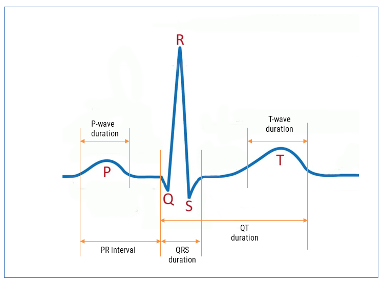
The ECG waveform can be split up into segments, where each wave or segment represents a certain event in the cardiac cycle, as shown below:
As seen, the biomedical features are designated P, Q, R, S, T that define points in time within the cardiac cycle. The RCF algorithm is further strengthened with our state-of-the-art AAE (Advanced Analytics Engine) that automatically cleans and find these features for clinical analysis.
AAE supported analytics
P-wave duration
PR interval
QRS duration
QT duration (Bazett algorithm used for QTc)
HR (RR interval)
HRV (rMSSD algorithm used)
Armed with the real-time features, an ML model can be trained and provide valuable insights into patient health running on an edge processor inside a wearable device.
A-Fib
Atrial fibrillation (A-Fib) is the most frequent cardiac arrhythmia, affecting millions of people worldwide. An arrhythmia is when the heart beats too slowly, too fast, or in an irregular way. Signs of A-Fib are an irregular beating pattern and no p-waves. Our AAE provides developers with all of the relevant features needed to build an ML model for robust A-Fib detection.
Let us help you build your product
By combining advanced low-power processor technology, advanced mathematical algorithmic concepts and medical knowledge, our solution provides developers with an easy way of building wearable products for medical use. The high accuracy of our Advanced Analytics Engine (AAE) has been verified by cardiologists, and can be used with an additional ML model or standalone to provide people with valuable insights into potentially fatal health conditions, such as A-Fib without the need for an expensive medical examination at a hospital.
ASN’s ECG algorithmic solutions are ideal for building next generation ECG and PPG wearable products on Arm Cortex-M microcontrollers (e.g. STM32F4, MAX32660) and bio-sensor SoCs (MAX86150). These algorithms can be easily used with industry standard biomedical AFEs, such as: MAX30003, AFE4500 and AFE4950.
Please contact us for more information and to arrange an evaluation.
Sanjeev is a RTEI (Real-Time Edge Intelligence) visionary and expert in signals and systems with a track record of successfully developing over 26 commercial products. He is a Distinguished Arm Ambassador and advises top international blue chip companies on their AIoT/RTEI solutions and strategies for I5.0, telemedicine, smart healthcare, smart grids and smart buildings.
ASN Filter Designer’s ANSI C SDK framework, provides developers with a comprehensive C code framework for developing AIoT filtering application on microcontrollers and embedded platforms. Although the framework has been primarily designed to support the just ASN filter Designer’s filter cascade, it is possible to create extra filter objects to augment the cascade.
Two common filtering methods used by AIoT developers are the Median and moving average (MA) filters. Although these fully integrated within the Framework’s filter cascade, it is often useful to have the flexibility of an additional filtering block to act as a post filter smoothing filter.
An extra median or MA filter may be easily added to main.c as shown below. Notice that data is filtered in blocks of 4 as required by the framework.
Median filter
The Median filter is non-linear filtering method that uses the concept of majority voting (i.e. calculating the median) to remove glitches and smooth data. It is edge preserving, making it a good choice for enhancing square waves or pulse like data.
[code language=”cpp”]
#include "ASN_DSP/DSPFilters/MedianFilter.h"
float InputTemp[4];
float OutputTemp[4];
MedianFilter_t MyMedianfilter;
InitMedianFilter(&MyMedianfilter,7); // median of length 7
for (n=0; n<TEST_LENGTH_SAMPLES; n+=4)
{
InputTemp[0]=InputValues[n];
InputTemp[1]=InputValues[n+1];
InputTemp[2]=InputValues[n+2];
InputTemp[3]=InputValues[n+3];
The moving average (MA) filter is optimal for reducing random noise while retaining a sharp step response, making it a versatile building block for smart sensor signal processing applications. It is perhaps one of the most widely used digital filters due to its conceptual simplicity and ease of implementation.
[code language=”cpp”]
#include "ASN_DSP/DSPFilters/MAFilter.h"
float InputTemp[4];
float OutputTemp[4];
MAFilter_t MyMAfilter;
InitMAFilter(&MyMAfilter,9); // MA of length 9
for (n=0; n<TEST_LENGTH_SAMPLES; n+=4)
{
InputTemp[0]=InputValues[n];
InputTemp[1]=InputValues[n+1];
InputTemp[2]=InputValues[n+2];
InputTemp[3]=InputValues[n+3];
Marty is an applications engineer and embedded software expert at ASN. He has over 10 years experience in developing high performance embedded libraries and applications for Arm processors.
https://www.advsolned.com/wp-content/uploads/2023/04/ansic-e1680791468445.png313400Marty de Vrieshttps://www.advsolned.com/wp-content/uploads/2021/07/asn_logo_red_met_tekst_helder-e1755353934770.pngMarty de Vries2023-04-06 15:25:212023-05-16 09:32:09How to add an extra MA or Median filter to the ASN DSP filtering ANSI C code framework
ASN Filter Designer’s new ANSI C SDK framework, provides developers with a comprehensive automatic C code generator for microcontrollers and embedded platforms. This allows developers to directly deploy their AIoT filtering application from within the tool to any STM32, Arduino, ESP32, PIC32, Beagle Bone and other Arm, RISC-V, MIPS microcontrollers for direct use.
Arm’s CMSIS-DSP library vs. ASN’s C SDK Framework
Thanks to our close collaboration with Arm’s architecture team, our new ultra-compact, highly optimised ANSI C based framework provides outstanding performance compared to other commercial DSP libraries, including Arm’s optimised CMSIS-DSP library.
Benchmarks for STM32: M3, M4F and M7F microcontrollers running an 8th order IIR biquad lowpass filter for 1024 samples
As seen, using o1 complier optimisation, our framework is able to surpass Arm’s CMSIS-DSP library’s performance on an M4F and M7F. Although notice that performance of both libraries is worse on the Cortex-M3, as it doesn’t have an FPU. Despite the difference, both libraries perform equally well, but the ASN DSP library has the added advantage of extra functionality and being platform agnostic, making it ideal for variety of biomedical (ECG, EMG, PPG), audio (sound effects, equalisers) , IoT (temperature, gas, pressure) and I4.0 (flow measurement, vibration analysis, CbM) applications.
AIoT applications designed on the newer Cortex-M33F and Cortex-M55F cores can also take advantage of extra filtering blocks, double precision arithmetic support, providing a simple way of implementing high performance AI on the Edge applications within hours.
Advantages for developers
A developer can now develop, test and deploy a complete DSP filtering application within the ASN Filter Designer within a few hours. This is very different from a traditional R&D approach that assigns a team of developers for several days in order to achieve the same level of accuracy required for the application.
Open source and agnostic code base: In order to allow developers to get the maximum performance for their applications, the ASN-DSP SDK is provided as open source and is written in ANSI C. This means that any embedded processor and any level of compiler optimisation can be used.
Memory size required for the ASN-DSP SDK is relativity lower than other standard DSP libraries, which makes the ASN-DSP SDK extremely suitable for microcontrollers that have memory constrains.
Using the ASN Filter Designer’s signal analyser tool, developers now can test the performance, accuracy and assess the frequency response of their designed filter and get optimised C code which they can directly use in their application.
The SDK also supports some extra filtering functions, such as: a median filter, a moving average filter, all-pass, single section IIR filters, a TKEO biomedical filter, and various non-linear functions, including RMS, Abs, Log and Sqrt. These functions form the filter cascade within the tool, and can be used to build signal processing applications, such as EMG and ECG biomedical applications.
The ASN-DSP SDK supports both single and double precision floating point arithmetic, providing excellent numerical accuracy and wide dynamic range. The library is unique in the sense that it supports double precision arithmetic, which although is not the most optimal for microcontrollers, allows for the implementation of high-fidelity filtering applications.
The ANSI C SDK framework is further extended by our new C# .NET framework, allowing .NET developers to build high performance desktop applications with signal processing capabilities.
Find out more and try it yourself
Benchmarks on a variety of 32-bit embedded platforms, including a biomedical EMG filtering example, are covered in the following application note.
The both framework SDKs are available in ASNFD v5.0, which may be downloaded here.
New book on Arm’s latest processors: The Definitive Guide to Arm Cortex-M23 and Cortex-M33 Processors. The book is written by Joseph Yiu, Arm’s resident architecture guru. It features benchmarks and experiments with our DSP filter design tooling (ASN Filter Designer) using CMSIS-DSP for Arm’s latest processors
We’re proud that Dr. Sanjeev Sarpal, Director of AI at Advanced Solutions Nederland has provided support in the digital filter design topic. We’re also very pleased to announce that Joseph Yiu’s new book features a chapter on the ASN Filter Designer for AI/IoT applications using the M23 and M33 Cortex-M cores. Advanced Solutions Nederland works closely with Arm’s DSP/architecture team for AI/DSP solutions using their cores. We’re currently working with Arm on releasing whitepapers on the Cortex-M55.
Armv8-M architecture and its features
The Definitive Guide to Arm® Cortex®-M23 and Cortex-M33 Processors focuses on the Armv8-M architecture and the features that are available in the Cortex-M23 and Cortex- M33 processors.
This book covers a range of topics, including:
the instruction set
the programmer’s model
interrupt handling
OS support
debug features
It demonstrates how to create software for the Cortex-M23 and Cortex-M33 processors by way of a range of examples. This enables embedded software developers to understand the Armv8-M architecture.
Worked out examples with ASN Filter Designer
Joseph Yiu’s new book features a chapter on the ASN Filter Designer for AI/IoT applications using the M23 and M33 Cortex-M cores. Our Director of AI, Dr. Sanjeev Sarpal, has provided support.
“The ASN Filter Designer Professional software supports a wide range of filter types. Its design allows filters to be designed via an interactive user interface, where various parameters can be adjusted and the design’s output can immediately be viewed. It also supports the simulation of the filter’s response so that the simulation outputs can be examined to determine whether the filter meets the requirements of the application. An added bonus, for developers creating software for Cortex-M processors, is that it generates C code that directly call CMSIS-DSP library functions (the designed filters can also be exported to C/C++, Python, Matlab, etc.).”
Defining the frequency response of the filter
“A number of commercial filter-design software tools are designed specifically for filter-design tasks and make it easier tot analyze a filters’ characteristics. For software developers who are not familiar with filter designs, these tools can be a great help” (p. 820). Thereby, Joseph Yiu uses the ASN Filter Designer for worked out examples. He creates a low pass biquad filter for a system with 48kHz sampling rate and with single-precision floating-point data type.
https://www.advsolned.com/wp-content/uploads/2021/03/Joseph-Yiu-Arm-Cortex-ASN-Filter-Designer-book.jpg427630ASN consultancy teamhttps://www.advsolned.com/wp-content/uploads/2021/07/asn_logo_red_met_tekst_helder-e1755353934770.pngASN consultancy team2021-03-16 12:30:532022-12-13 16:07:28New book: "Definitive Guide to Arm Cortex-M23 and Cortex-M33 Processors” by Joseph Yiu
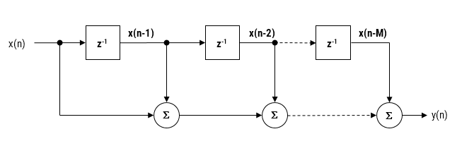
As discussed in a previous article, the moving average (MA) filter is perhaps one of the most widely used digital filters due to its conceptual simplicity and ease of implementation. The realisation diagram shown below, illustrates that an MA filter can be implemented as a simple FIR filter, just requiring additions and a delay line.
Modelling the above, we see that a moving average filter of length \(\small\textstyle L\) for an input signal \(\small\textstyle x(n)\) may be defined as follows:
This computation requires \(\small\textstyle L-1\) additions, which may become computationally demanding for very low power processors when \(\small\textstyle L\) is large. Therefore, applying some lateral thinking to the computational challenge, we see that a much more computationally efficient filter can be used in order to achieve the same result, namely:
Notice that this implementation only requires one addition and one subtraction for any value of \(\small\textstyle L\). A further simplification (valid for both implementations) can be achieved in a pre-processing step prior to implementing the difference equation, i.e. scaling all input values by \(\small\textstyle L\). If \(\small\textstyle L\) is a power of two (e.g. 4,8,16,32..), this can be achieved by a simple binary shift right operation.
Is it an IIR or actually an FIR?
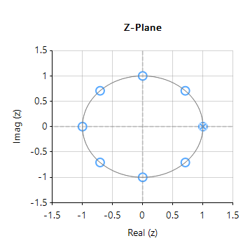
Upon initial inspection of the transfer function of Eqn. \(\small\textstyle\eqref{TF}\), it appears that the efficient Moving average filter is an IIR filter. However, analysing the pole-zero plot of the filter (shown on the right for \(\small\textstyle L=8\)), we see that the pole at DC has been cancelled by a zero, and that the resulting filter is actually an FIR filter, with the same result as Eqn. \(\small\textstyle\eqref{FIRdef}\).
Notice also that the frequency spacing of the zeros (corresponding to the nulls in the frequency response) are at spaced at \(\small\textstyle\pm\frac{Fs}{L}\). This can be readily seen for this example, where an MA of length 8, sampled at \(\small\textstyle 500Hz\), results in a \(\small\textstyle\pm62.5Hz\) resolution.
As a final point, notice that the our efficient filter requires a delay line of length \(\small\textstyle L+1\), compared with the FIR delay line of length, \(\small\textstyle L\). However, this is a small price to pay for the computation advantage of a filter just requiring one addition and one subtraction. As such, the MA filter of Eqn. \(\small\textstyle\eqref{TF}\) presented herein is very attractive for very low power processors, such as the Arm Cortex-M0 that have been traditionally overlooked for DSP operations.
Implementation
The MA filter of Eqn. \(\small\textstyle\eqref{TF}\) may be implemented in ASN FilterScript as follows:
ClearH1;  // clear primary filter from cascade
interface L = {2,32,2,4}; // interface variable definition

Main()
Num = {1,zeros(L-1),-1}; // define numerator coefficients
Den = {1,-1}; // define denominator coefficients
Gain = 1/L; // define gain
In ECG signal processing, the Removal of 50/60Hz powerline interference from delicate information rich ECG biomedical waveforms is a challenging task! The challenge is further complicated by adjusting for the effects of EMG, such as a patient limb/torso movement or even breathing. A traditional approach adopted by many is to use a 2nd order IIR notch filter:
where, \(w_o=\frac{2\pi f_o}{fs}\) controls the centre frequency, \(f_o\) of the notch, and \(r=1-\frac{\pi BW}{fs}\) controls the bandwidth (-3dB point) of the notch.
What’s the challenge?
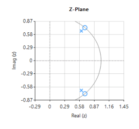
As seen above, \(H(z) \) is simple to implement, but the difficulty lies in finding an optimal value of \(r\), as a desirable sharp notch means that the poles are close to unit circle (see right).
In the presence of stationary interference, e.g. the patient is absolutely still and effects of breathing on the sensor data are minimal this may not be a problem.
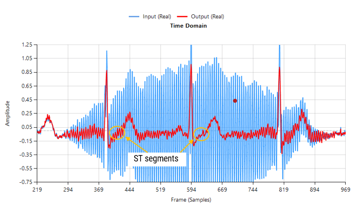
However, when considering the effects of EMG on the captured waveform (a much more realistic situation), the IIR filter’s feedback (poles) causes ringing on the filtered waveform, as illustrated below:
Contaminated ECG with non-stationary 50Hz powerline interference (IIR filtering)
As seen above, although a majority of the 50Hz powerline interference has been removed, there is still significant ringing around the main peaks (filtered output shown in red). This ringing is undesirable for many biomedical applications, as vital cardiac information such as the ST segment cannot be clearly analysed.
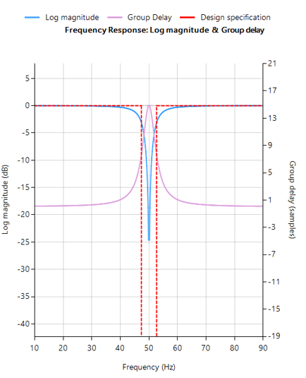
The frequency reponse of the IIR used to filter the above ECG data is shown below.
IIR notch filter frequency response
Analysing the plot it can be seen that the filter’s group delay (or average delay) is non-linear but almost zero in the passbands, which means no distortion. The group delay at 50Hz rises to 15 samples, which is the source of the ringing – where the closer to poles are to unit circle the greater the group delay.
ASN FilterScript offers designers the notch() function, which is a direct implemention of H(z), as shown below:
ClearH1;  // clear primary filter from cascade
ShowH2DM;   // show DM on chart

interface BW={0.1,10,.1,1};

Main()

F=50;
Hd=notch(F,BW,"symbolic");
Num = getnum(Hd); // define numerator coefficients
Den = getden(Hd); // define denominator coefficients
Gain = getgain(Hd); // define gain
Savitzky-Golay FIR filters
A solution to the aforementioned mentioned ringing as well as noise reduction can be achieved by virtue of a Savitzky-Golay lowpass smoothing filter. These filters are FIR filters, and thus have no feedback coefficients and no ringing!
Savitzky-Golay (polynomial) smoothing filters or least-squares smoothing filters are generalizations of the FIR average filter that can better preserve the high-frequency content of the desired signal, at the expense of not removing as much noise as an FIR average. The particular formulation of Savitzky-Golay filters preserves various moment orders better than other smoothing methods, which tend to preserve peak widths and heights better than Savitzky-Golay. As such, Savitzky-Golay filters are very suitable for biomedical data, such as ECG datasets.
Eliminating the 50Hz powerline component
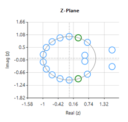
Designing an 18th order Savitzky-Golay filter with a 4th order polynomial fit (see the example code below), we obtain an FIR filter with a zero distribution as shown on the right. However, as we wish to eliminate the 50Hz component completely, the tool’s P-Z editor can be used to nudge a zero pair (shown in green) to exactly 50Hz.
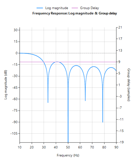
The resulting frequency response is shown below, where it can be seen that there is notch at exactly 50Hz, and the group delay of 9 samples (shown in purple) is constant across the frequency band.
FIR Savitzky-Golay filter frequency response
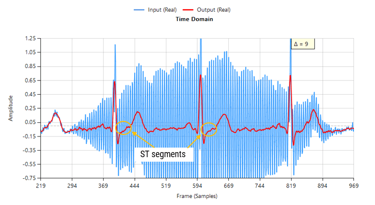
Passing the tainted ECG dataset through our tweaked Savitzky-Golay filter, and adjusting for the group delay we obtain:
Contaminated ECG with non-stationary 50Hz powerline interference (FIR filtering)
As seen, there are no signs of ringing and the ST segments are now clearly visible for analysis. Notice also how the filter (shown in red) has reduced the measurement noise, emphasising the practicality of Savitzky-Golay filter’s for biomedical signal processing.
A Savitzky-Golay may be designed and optimised in ASN FilterScript via the savgolay() function, as follows:
ClearH1;  // clear primary filter from cascade

interface L = {2, 50,2,24};
interface P = {2, 10,1,4};

Main()

Hd=savgolay(L,P,"numeric");  // Design Savitzky-Golay lowpass
Num=getnum(Hd);
Den={1};
Gain=getgain(Hd);
Deployment
This filter may now be deployed to variety of domains via the tool’s automatic code generator, enabling rapid deployment in Matlab, Python and embedded Arm Cortex-M devices.
Sanjeev is a RTEI (Real-Time Edge Intelligence) visionary and expert in signals and systems with a track record of successfully developing over 26 commercial products. He is a Distinguished Arm Ambassador and advises top international blue chip companies on their AIoT/RTEI solutions and strategies for I5.0, telemedicine, smart healthcare, smart grids and smart buildings.
Infinite impulse response (IIR) filters are useful for a variety of sensor measurement applications, including measurement noise removal and unwanted component cancellation, such as powerline interference. Although several practical implementations for the IIR exist, the Direct form II Transposed structure offers the best numerical accuracy for floating point implementation. However, when considering fixed point implementation on a microcontroller, the Direct Form I structure is considered to be the best choice by virtue of its large accumulator that accommodates any intermediate overflows. This application note specifically addresses IIR biquad filter design and implementation on a Cortex-M based microcontroller with the ASN Filter Designer for both floating point and fixed point applications via the Arm CMSIS-DSP software framework.
Details are also given (including a reference example project) regarding implementation of the IIR filter in Arm/Keil’s MDK industry standard Cortex-M microcontroller development kit.
Introduction
ASN Filter Designer provides engineers with a powerful DSP experimentation platform, allowing for the design, experimentation and deployment of complex IIR and FIR (finite impulse response) digital filter designs for a variety of sensor measurement applications. The tool’s advanced functionality, includes a graphical based real-time filter designer, multiple filter blocks, various mathematical I/O blocks, live symbolic math scripting and real-time signal analysis (via a built-in signal analyser). These advantages coupled with automatic documentation and code generation functionality allow engineers to design and validate a digital filter within minutes rather than hours.
The Arm CMSIS-DSP (Cortex Microcontroller Software Interface Standard) software framework is a rich collection of over sixty DSP functions (including various mathematical functions, such as sine and cosine; IIR/FIR filtering functions, complex math functions, and data types) developed by Arm that have been optimised for their range of Cortex-M processor cores.
The framework makes extensive use of highly optimised SIMD (single instruction, multiple data) instructions, that perform multiple identical operations in a single cycle instruction. The SIMD instructions (if supported by the core) coupled together with other optimisations allow engineers to produce highly optimised signal processing applications for Cortex-M based micro-controllers quickly and simply.
ASN Filter Designer fully supports the CMSIS-DSP software framework, by automatically producing optimised C code based on the framework’s DSP functions via its code generation engine.
Designing IIR filters with the ASN Filter Designer
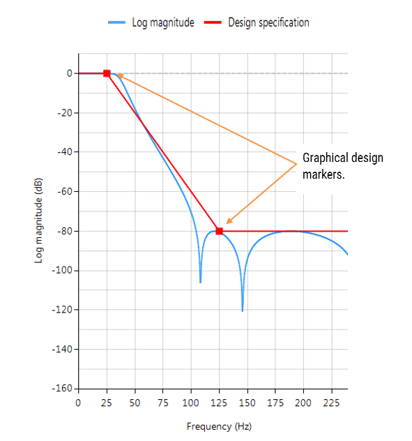
ASN Filter Designer provides engineers with an easy to use, intuitive graphical design development platform for both IIR and FIR digital filter design. The tool’s real-time design paradigm makes use of graphical design markers, allowing designers to simply draw and modify their magnitude frequency response requirements in real-time while allowing the tool automatically fill in the exact specifications for them.
Consider the design of the following technical specification:
Fs:
500Hz
Passband frequency:
0-40Hz
Type:
Lowpass
Method:
Elliptic
Stopband attenuation @ 125Hz:
≥ 80 dB
Passband ripple:
< 0.1dB
Order:
Small as possible
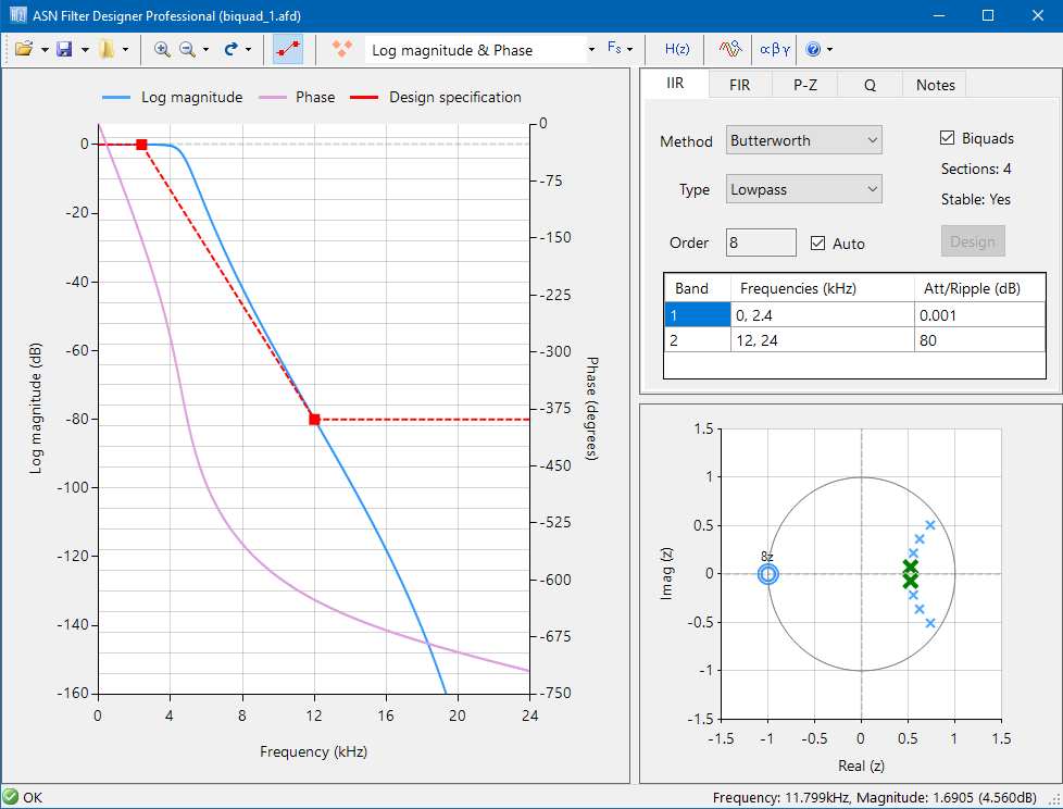
Graphically entering the specifications into the ASN Filter Designer, and fine tuning the design marker positions, the tool automatically designs the filter as a Biquad cascade (this terminology will be discussed in the following sections), automatically choosing the required filter order, and in essence – automatically producing the filter’s exact technical specification!
The frequency response of a 5th order IIR Elliptic Lowpass filter meeting the specifications is shown below:
This 5th order Lowpass filter will form the basis of the discussion presented herein.
Biquad IIR filters
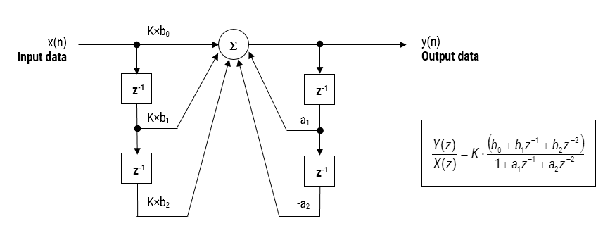
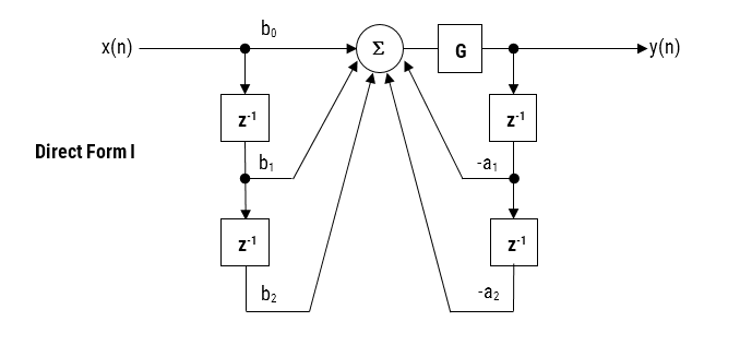
The IIR filter implementation discussed herein is said to be biquad, since it has two poles and two zeros as illustrated below in Figure 1. The biquad implementation is particularly useful for fixed point implementations, as the effects of quantization and numerical stability are minimised. However, the overall success of any biquad implementation is dependent upon the available number precision, which must be sufficient enough in order to ensure that the quantised poles are always inside the unit circle.
Figure 1: Direct Form I (biquad) IIR filter realization and transfer function.
Analysing Figure 1, it can be seen that the biquad structure is actually comprised of two feedback paths (scaled by \(a_1\) and \(a_2\)), three feed forward paths (scaled by \(b_0, b_1\) and \(b_2\)) and a section gain, \(K\). Thus, the filtering operation of Figure 1 can be summarised by the following simple recursive equation:
Analysing the equation, notice that the biquad implementation only requires four additions (requiring only one accumulator) and five multiplications, which can be easily accommodated on any Cortex-M microcontroller. The section gain, \(K\) may also be pre-multiplied with the forward path coefficients before implementation.
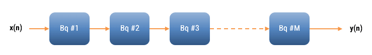
A collection of Biquad filters is referred to as a Biquad Cascade, as illustrated below.
The ASN Filter Designer can design and implement a cascade of up to 50 biquads (Professional edition only).
Floating point implementation
When implementing a filter in floating point (i.e. using double or single precision arithmetic) Direct Form II structures are considered to be a better choice than the Direct Form I structure. The Direct Form II Transposed structure is considered the most numerically accurate for floating point implementation, as the undesirable effects of numerical swamping are minimised as seen by analysing the difference equations.
Figure 2 – Direct Form II Transposed strucutre, transfer function and difference equations
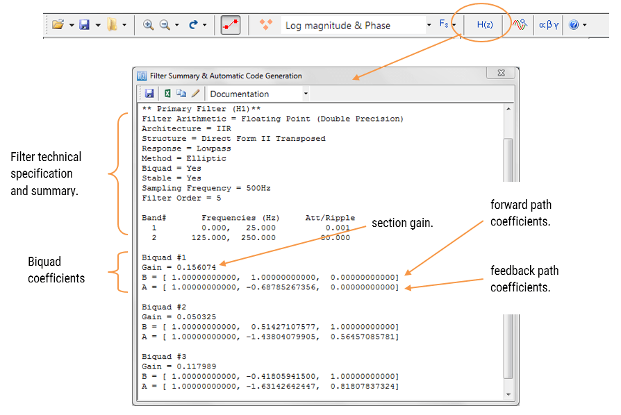
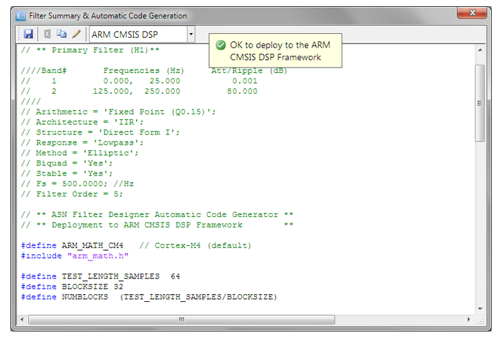
The filter summary (shown in Figure 3) provides the designer with a detailed overview of the designed filter, including a detailed summary of the technical specifications and the filter coefficients, which presents a quick and simple route to documenting your design.
The ASN Filter Designer supports the design and implementation of both single section and Biquad (default setting) IIR filters. However, as the CMSIS-DSP framework does not directly support single section IIR filters, this feature will not be covered in this application note.
The CMSIS-DSP software framework implementation requires sign inversion (i.e. flipping the sign) of the feedback coefficients. In order to accommodate this, the tool’s automatic code generation engine automatically flips the sign of the feedback coefficients as required. In this case, the set of difference equations become,
Automatic code generation to Arm processor cores via CMSIS-DSP
The ASN Filter Designer’s automatic code generation engine facilitates the export of a designed filter to Cortex-M Arm based processors via the CMSIS-DSP software framework. The tool’s built-in analytics and help functions assist the designer in successfully configuring the design for deployment.
All floating point IIR filters designs should be based on Single Precision arithmetic and either a Direct Form I or Direct Form II Transposed filter structure, as this is supported by a hardware multiplier in the M4F, M7F, M33F and M55F cores. Although you may choose Double Precision, hardware support is only available in some M7F and M55F Helium devices. As discussed in the previous section, the Direct Form II Transposed structure is advocated for floating point implementation by virtue of its higher numerically accuracy.
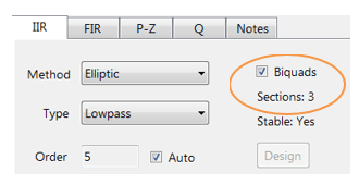
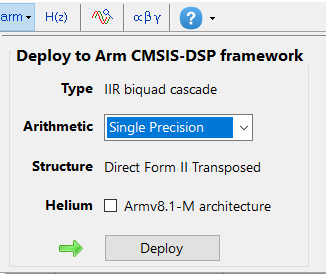
Quantisation and filter structure settings can be found under the Q tab (as shown on the left). Setting Arithmetic to Single Precision and Structure to Direct Form II Transposed and clicking on the Apply button configures the IIR considered herein for the CMSIS-DSP software framework.
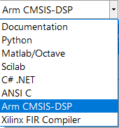
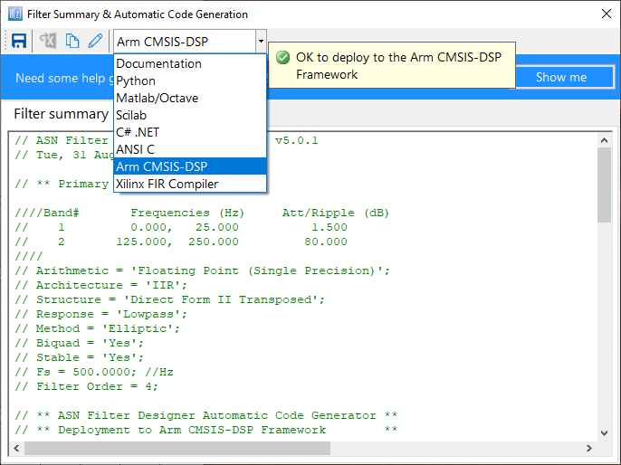
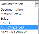
Select the Arm CMSIS-DSP framework from the selection box in the filter summary window:
The automatically generated C code based on the CMSIS-DSP framework for direct implementation on an Arm based Cortex-M processor is shown below:
As seen, the automatic code generator generates all initialisation code, scaling and data structures needed to implement the IIR via the CMSIS-DSP library. This code may be directly used in any Cortex-M based development project – a complete Keil MDK example is available on Arm/Keil’s website. Notice that the tool’s code generator produces code for the Cortex-M4 core as default, please refer to the table below for the #define definition required for all supported cores.
ARM_MATH_CM0
Cortex-M0 core.
ARM_MATH_CM4
Cortex-M4 core.
ARM_MATH_CM0PLUS
Cortex-M0+ core.
ARM_MATH_CM7
Cortex-M7 core.
ARM_MATH_CM3
Cortex-M3 core.
ARM_MATH_ARMV8MBL
ARMv8M Baseline target (Cortex-M23 core).
ARM_MATH_ARMV8MML
ARMv8M Mainline target (Cortex-M33 core).
Automatic code generation of complex coefficient IIR filters is currently not supported (see below for more information).
Arm deployment wizard
Professional licence users may expedite the deployment by using the Arm deployment wizard. The built in AI will automatically determine the best settings for your design based on the quantisation settings chosen.
The built in AI automatically analyses your complete filter cascade and converts any H2 or Heq filters into an H1 for implementation. A complex coefficient filter will be automatically converted to real filter for implementation.
Implementing the filter in Arm Keil’s MDK
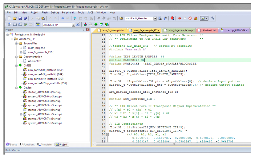
As mentioned in the previous section, the code generated by the Arm CMSIS-DSP code generator may be directly used in any Cortex-M based development project tooling, such as Arm Keil’s industry standard μVision MDK (microcontroller development kit).
A complete μVision example IIR biquad filter project can be downloaded from Keil’s website, and as seen below is as simple as copying and pasting the code and making minor adjustments to the code.
The example project makes use of μVision’s powerful simulation capabilities, allowing for the evaluation of the IIR filter on M0, M3, M4 and M7 cores respectively. As an added bonus, μVision’s logic analyser may also be used, allowing for comparisons between the ASN Filter Designer’s signal analyser and the reality on a Cortex-M core.
Fixed point implementation
As aforementioned, the Direct Form I filter structure is the best choice for fixed point implementation. However, before implementing the difference equation on a fixed point processor, several important data scaling considerations must be taken into account. As the CMSIS-DSP framework only supports Q15 and Q31 data types for IIR filters, the following discussion relates to an implementation on a 16-bit word architecture, i.e. Q15.
Quantisation
In order to correctly represent the coefficients and input/output numbers, the system word length (16-bit for the purposes of this application note) is first split up into its number of integers and fractional components. The general format is given by:
Q Num of Integers.Fraction length
If we assume that all of data values lie within a maximum/minimum range of \(\pm 1\), we can use Q0.15 format to represent all of the numbers respectively. Notice that Q0.15 (or simply Q15) format represents a maximum of \(\displaystyle 1-2^{-15}=0.9999=0x7FFF\) and a minimum of \(-1=0x8000\) (two’s complement format).
The ASN Filter Designer may be configured for Fixed Point Q15 arithmetic by setting the Word length and Fractional length specifications in the Q Tab (see the configuration section for the details). However, one obvious problem that manifests itself for Biquads is the number range of the coefficients. As poles can be placed anywhere inside the unit circle, the resulting polynomial needed for implementation will often be in the range \(\pm 2\), which would require Q14 arithmetic. In order to overcome this issue, all numerator and denominator coefficients are scaled via a biquad Post Scaling Factor as discussed below.
Post Scaling Factor
In order to ensure that coefficients fit within the Word length and Fractional length specifications, all IIR filters include a Post Scaling Factor, which scales the numerator and denominator coefficients accordingly. As a consequence of this scaling, the Post Scaling Factor must be included within the filter structure in order to ensure correct operation.
The Post scaling concept is illustrated below for a Direct Form I biquad implementation.
Figure 4: Direct Form I structure with post scaling.
Pre-multiplying the numerator coefficients with the section gain, \(K\), each coefficient can now be scaled by \(G\), i.e. \(\displaystyle b_0=\frac{b_0}{G}, b_1=\frac{b_1}{G}, a_1=\frac{a_1}{G}, a_2=\frac{a_2}{G}\) and etc. This now results in the following difference equation:
All IIR structures implemented within the tool include the Post Scaling Factor concept. This scaling is mandatory for implementation via the Arm CMSIS-DSP framework – see the configuration section for more details.
Understanding the filter summary
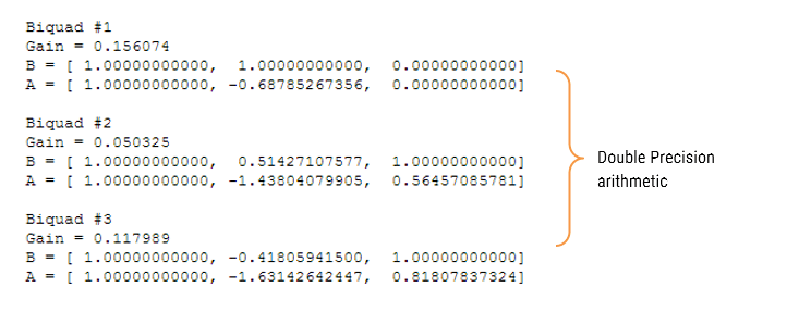
In order to fully understand the information presented in the ASN Filter Designer filter summary, the following example illustrates the filter coefficients obtained with Double Precision arithmetic and with Fixed Point Q15 quantisation.
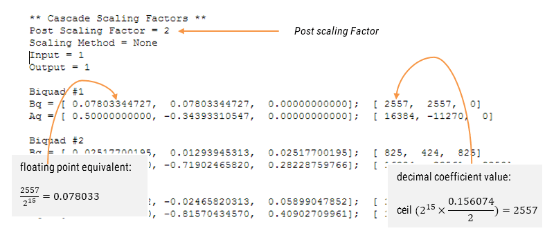
Applying Fixed Point Q15 arithmetic (note the effects of quantisation on the coefficient values):
Configuring the ASN Filter Designer for Fixed Point arithmetic
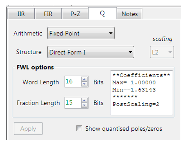
In order to implement an IIR fixed point filter via the CMSIS-DSP framework, all designs must be based on Fixed Point arithmetic (either Q15 or Q31) and the Direct Form I filter structure.
Quantisation and filter structure settings can be found under the Q tab (as shown on the left): Setting Arithmetic to Fixed Point and Structure to Direct Form I and clicking on the Apply button configures the IIR considered herein for the CMSIS-DSP software framework.
The Post Scaling Factor is actually implemented in the CMSIS-DSP software framework as \( \log_2 G\) (i.e. a shift left scaling operation as depicted in Figure 4).
Built in analytics: the tool will automatically analyse the cascade’s filter coefficients and choose an appropriate scaling factor. As seen above, as the largest minimum value is -1.63143, thus, a Post Scaling Factor of 2 is required in order to ‘fit’ all of the coefficients into Q15 arithmetic.
Comparing spectra obtained by different arithmetic rules
In order to improve clarity and overall computation speed, the ASN Filter Designer only displays spectra (i.e. magnitude, phase etc.) based on the current arithmetic rules. This is somewhat different to other tools that display multi-spectra obtained by (for example) Fixed Point and Double Precision arithmetic. For any users wishing to compare spectra you may simply switch between arithmetic settings by changing the Arithmetic method. The designer will then automatically re-compute the filter coefficients using the selected arithmetic rules and the current technical specification. The chart will then be updated using the current zoom settings.
Automatic code generation to the Arm CMSIS-DSP framework
As with floating point arithmetic, select the Arm CMSIS-DSP framework from the selection box in the filter summary window:
The automatically generated C code based on the CMSIS-DSP framework for direct implementation on an Arm based Cortex-M processor is shown below:
As with the floating point filter, the automatic code generator generates all initialisation code, scaling and data structures needed to implement the IIR via the CMSIS-DSP library. This code may be directly used in any Cortex-M based development project – a complete Keil MDK example is available on Arm/Keil’s website. Notice that the tool’s code generator produces code for the Cortex-M4 core as default, please refer to the table below for the #define definition required for all supported cores.
ARM_MATH_CM0
Cortex-M0 core.
ARM_MATH_CM4
Cortex-M4 core.
ARM_MATH_CM0PLUS
Cortex-M0+ core.
ARM_MATH_CM7
Cortex-M7 core.
ARM_MATH_CM3
Cortex-M3 core.
ARM_MATH_ARMV8MBL
ARMv8M Baseline target (Cortex-M23 core).
ARM_MATH_ARMV8MML
ARMv8M Mainline target (Cortex-M33 core).
The main test loop code (not shown) centres around the arm_biquad_cascade_df2T_f32() function, which performs the filtering operation on a block of input data.
Complex coefficient IIR filters are currently not supported.
Validating the design with the signal analyser
A design may be validated with the signal analyser, where both time and frequency domain plots are supported. A comprehensive signal generator is fully integrated into the signal analyser allowing designers to test their filters with a variety of input signals, such as sine waves, white noise or even external test data.
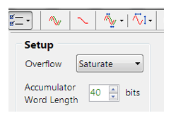
For Fixed Point implementations, the tool allows designers to specify the Overflow arithmetic rules as: Saturate or Wrap. Also, the Accumulator Word Length may be set between 16-40 bits allowing designers to quickly find the optimum settings to suit their application.
Extra resources
Digital signal processing: principles, algorithms and applications, J.Proakis and D.Manoloakis
Digital signal processing: a practical approach, E.Ifeachor and B.Jervis.
Digital filters and signal processing, L.Jackson.
Step by step video tutorial of designing an IIR and deploying it to Keil MDK uVision.
Implementing Biquad IIR filters with the ASN Filter Designer and the Arm CMSIS-DSP software framework (ASN-AN025)
Sanjeev is a RTEI (Real-Time Edge Intelligence) visionary and expert in signals and systems with a track record of successfully developing over 26 commercial products. He is a Distinguished Arm Ambassador and advises top international blue chip companies on their AIoT/RTEI solutions and strategies for I5.0, telemedicine, smart healthcare, smart grids and smart buildings.
https://www.advsolned.com/wp-content/uploads/2018/09/asn25_biquad_postscale.png316678Dr. Sanjeev Sarpalhttps://www.advsolned.com/wp-content/uploads/2021/07/asn_logo_red_met_tekst_helder-e1755353934770.pngDr. Sanjeev Sarpal2018-09-22 22:44:112023-05-12 16:39:11Implementing Biquad IIR filters with the ASN Filter Designer and the Arm CMSIS-DSP software framework