Posts

We live in a time where wearable/mobile products comprised of sensors, apps, AI and IoT (AIoT) technology are part of everyday life. Every year we hear about amazing advances in processor technology and AI algorithms for all aspects of life from industrial automation to futuristic biomedical products.

For developers, the requirement to design low-cost products with better battery life, higher computational performance and analytical accuracy, requires access to a suite of affordable processor technology, algorithmic libraries, design tooling and support.

This article aims to provide developers with an overview of all salient points required for algorithm implementation on Arm Cortex-M processors.

Can you give me a concrete example?

Almost all IoT sensor applications require some level of signal processing to enhance data and extract features of interest. This could be temperature, humidity, gas, current, voltage, audio/sound, accelerometer data or even biomedical data.  

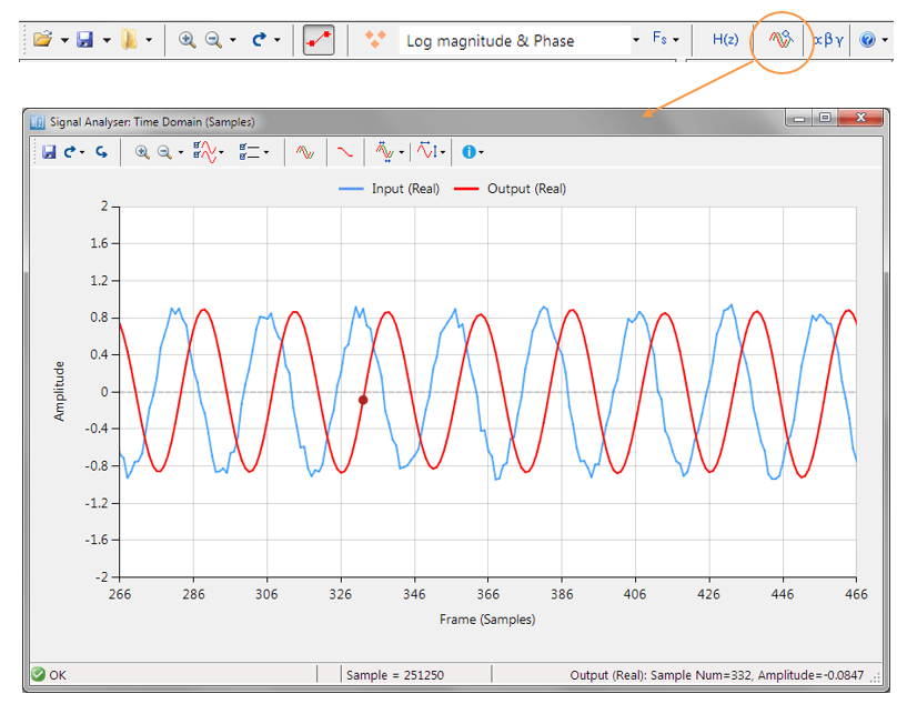
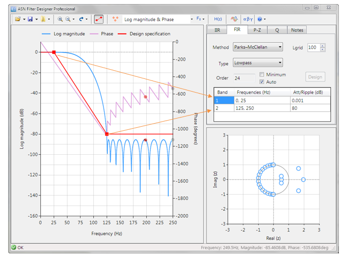
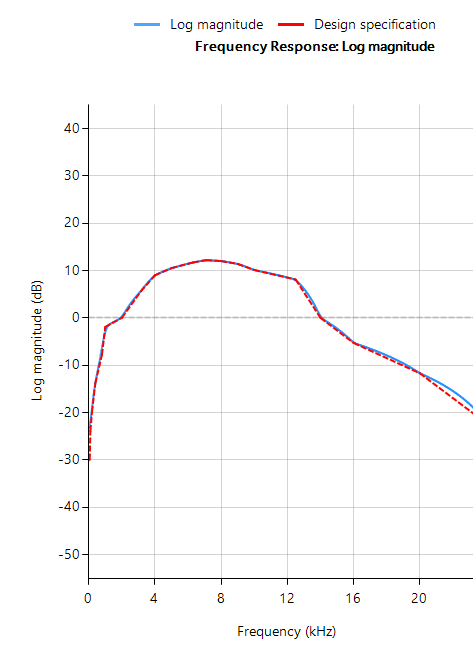
Consider the following application for gas concentration measurement from an Infra-red gas sensor. The requirement is to determine the amplitude of the sinusoid in order to get an estimate of gas concentration – where the bigger amplitude is the higher the gas concentration will be.

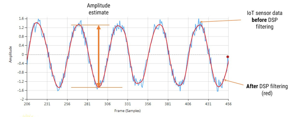
Analysing the figure, it can be seen that the sinusoid is corrupted with measurement noise (shown in blue), and any estimate based on the blue signal will have a high degree of uncertainty about it – which is not very useful for getting an accurate reading of gas concentration!

After cleaning the sinusoid with a digital filter (red line), we obtain a much more accurate and usable signal for our gas concentration estimation challenge. But how do we obtain the amplitude?

Knowing that the gradient at the peaks is zero, a relativity easy and robust way of finding the peaks of the sinusoid is via numerical differentiation, i.e. computing the difference between sample values and then looking for the zero-crossing points in the differentiated data. Armed with the positions and amplitudes of the peaks, we can take the average and easily obtain the amplitude and frequency.  Notice that any DC offsets and low-frequency baseline wander will be removed via the differentiation operation.

This is just a simple example of how to extract the properties of a sinusoid in real-time using various algorithmic IP blocks. There are of course a number of other methods that may be used, such as complex filters (analytic signals), Kalman filters and the FFT (Fast Fourier Transform).

Arm Cortex-M processor technology

Although a few processor technologies exist for microcontrollers (e.g. RISC-V, Xtensa, MIPS), over 90% of the microcontrollers used in the smart product market are powered by so-called Arm Cortex-M processors that offer a combination of high algorithmic performance, low-power and security. The Arm Cortex-M4 is a very popular choice with several silicon vendors (including ST, TI, NXP, ADI, Nordic, Microchip, Renesas), as it offers DSP (digital signal processing) functionality traditionally found in more expensive devices and is low-power.

Algorithmic libraries and support

An obvious hurdle for many developers is how to port their algorithmic concept or methods from Python/Matlab into embedded C for real-time operation? This is easier said than done, as many software engineers are not well-versed in understanding the mathematical concepts needed to implement algorithms. This is further complicated by the challenge of how to implement algorithms developed by researchers that are not interested/experienced in developing real-time embedded applications.

A possible solution offered by the Mathworks (Embedded Coder) automatically translates Matlab algorithms and functions into C for Arm processors, but its high price tag and steep learning curve make it unattractive for many.

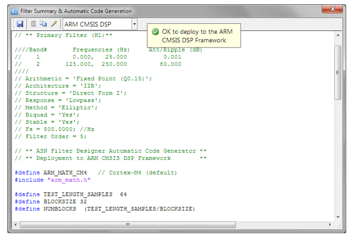
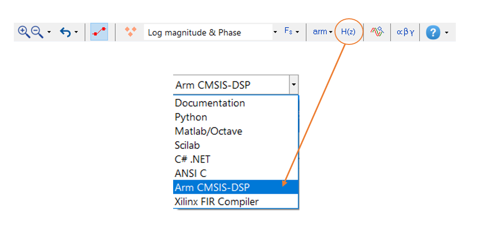
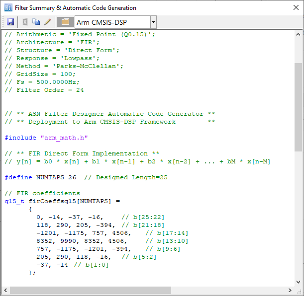
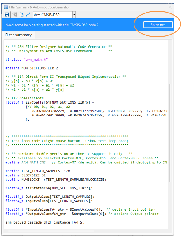
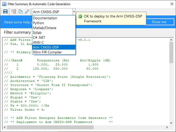
That being said, Arm and its rich ecosystem of partners provide developers with extensive easy-to-use tooling and tried and tested software libraries. Arm’s CMSIS-DSP and CMSIS-NN frameworks for algorithm development and machine learning (ML) are two very popular examples that are open source and are used internationally by tens of thousands of developers.

The Arm CMSIS-DSP software framework is particularly interesting as it provides IoT developers with a rich collection of fast mathematical and vector functions, interpolation functions, digital filtering (FIR/IIR) and adaptive filtering (LMS) functions, motor control functions (e.g. PID controller), complex math functions and supports various data types, including fixed and floating point. The important point to make here is that all of these functions have been optimised for Arm Cortex-M processors, allowing you to focus on your application rather than worrying about optimisation.  

The Arm-CMSIS framework solutions are strengthened by Arm partners ASN and Qeexo who provide developers with easy-to-use real-time filtering, feature extraction and ML tooling (AutoML) and reference designs, expediting the development of IoT applications, including industrial, audio and biomedical. These solutions have been optimised for Arm processors with the help of Arm’s architecture experts and insider knowledge of compiler workings.

A benchmark of ASN’s floating point application-specific DSP filtering library versus Arm’s CMSIS-DSP library is shown below for three types of Arm cores.

Framework Benchmarks: lower number of clock cycles means higher performance.

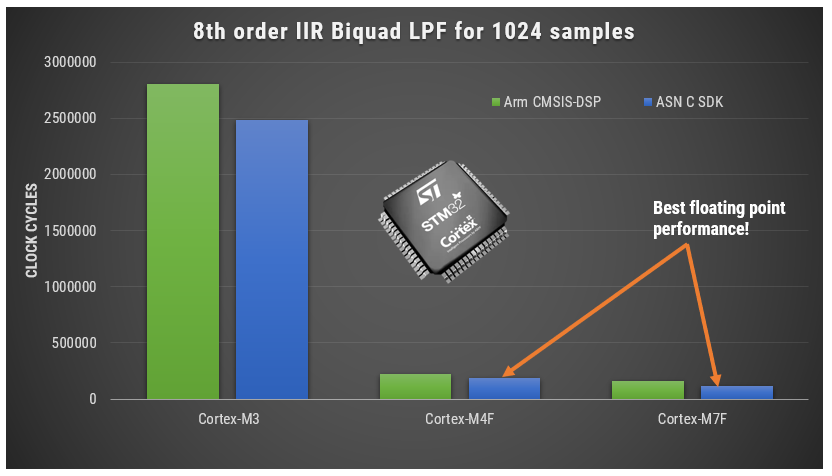
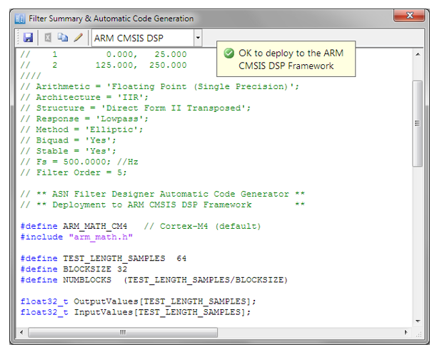
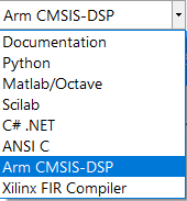
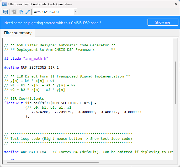
As seen, the performance of the ASN library is slightly faster by virtue of the application-specific nature of the implementation. The C code is automatically generated from the ASN Filter Designer tool.

Cortex-M4 and Cortex-M7

The Arm Cortex-M4 processor and its more powerful bigger brother the Cortex-M7 are highly-efficient embedded processors designed for IoT applications that require decent real-time signal processing performance and memory.

Both the Cortex-M4 and M7 core benefit from the Armv7E-M architecture that offers additional DSP extensions. Depending on the flavour of the processor, the M4F/M7F processors implement DSP hardware accelerated instructions (SIMD), as well as hardware floating point support via an FPU (floating point unit), giving them a significant performance boost over the Cortex-M3. The ‘F’ suffix signifies that the device has an FPU.

This lends itself to the efficient implementation of much more computationally intensive DSP and ML algorithms needed for more advanced IoT products and real-time control applications requiring highly deterministic operations.

Microcontrollers based on the M4F or M7F, usually offer many of the hardware peripheral and connectivity advantages of the simpler M3, providing developers with a very powerful, low-power development platform for their IoT application. The Cortex-M7F typically offers much higher performance than its Cortex-M4F little brother, doubling the performance on FFT, digital filters and other critical algorithms.

Floating point or fixed point?

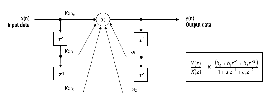
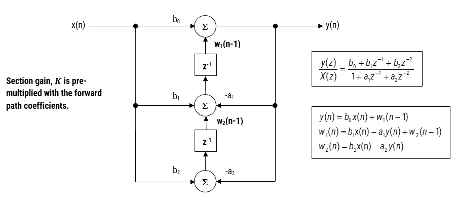
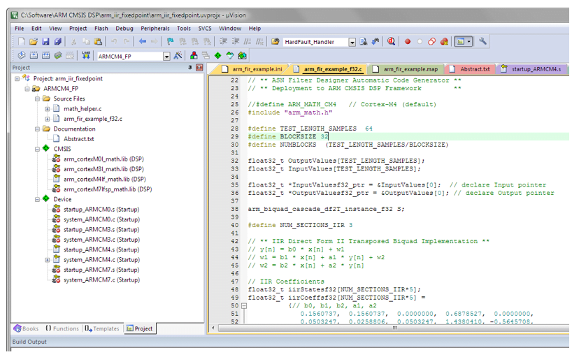
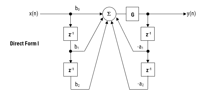
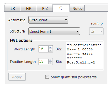
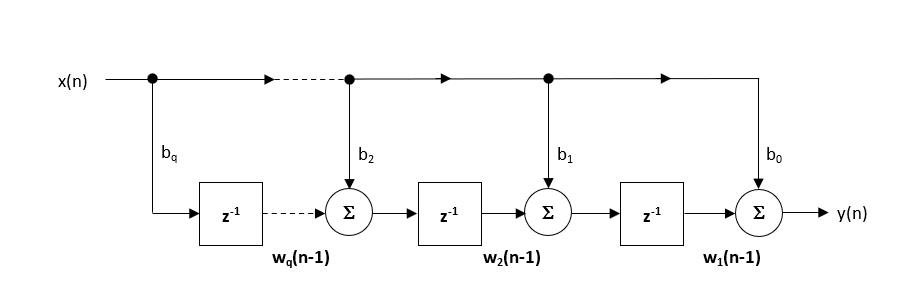
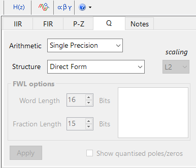
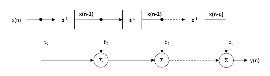
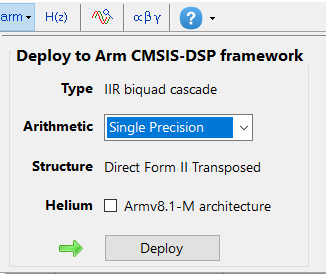
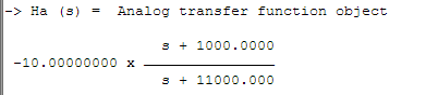
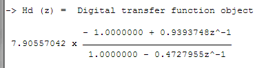
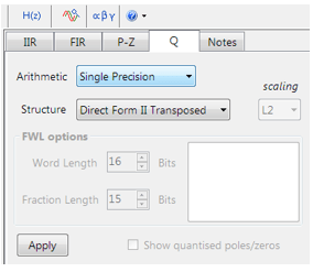
The hardware floating point support unit expedites RAD (rapid application development), as algorithms and functions developed in Matlab or Python can be ported to C for implementation without the need for a lengthy data arithmetic quantisation analysis. Although floating point comes with its own problems, such as numeric swamping, whereby adding a large number to a small number ignores the smaller component. This can become troublesome in digital filtering applications using the standard Direct Form structure. It is for this reason that all floating-point filters should be implemented using the Direct Form Transposed structure, as discussed in the following article.

Correctly designing and implementing these tricks requires specialist knowledge of signal processing and C programming, which may not always be available within an organisation. This becomes even more frustrating when implementing new algorithms and concepts, where the effects of the arithmetic are yet to be determined.

Single vs double precision floating point

For a majority of IoT applications single precision (32-bit) floating point arithmetic will be sufficient, providing approximately 7 significant digits of precision. Double precision (64-bit) floating point provides approximately 15 significant digits of precision, but in truth should only be used in applications that require more than 7 significant digits of precision. Some examples include: FFT based noise cancellation, CIC correction filters and Rogowski coil compensation filters. 

Some Cortex-M7F’s (e.g. STM32F769) implement a Double precision FPU providing an extra performance boost to high numerical accuracy IoT applications.
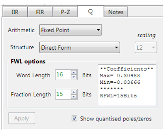
Fixed point

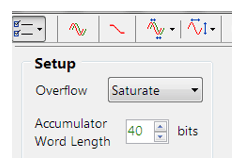
Fixed point is not necessarily less accurate than floating point, but requires much more quantisation analysis, which becomes tricky for signals with a wide dynamic range. As with floating point careful analysis is required, as weird effects can appear due to the level of quantisation used, leading to unreliable behaviour if not properly investigated. It is this challenge that can slow down a development cycle significantly, in some cases taking months to validate a new algorithm.

Many developers have traditionally considered devices without an FPU (e.g., Cortex-M0/M3) as the best choice for low-power battery applications. However, when comparing a modern Cortex-M7 device manufactured using 40nm semiconductor process technology, to that of a ten-year-old Cortex-M3 using 180nm process technology, the Cortex-M7 device will likely have a lower power profile.

Acceleration of DSP calculations

The Armv7E-M architecture supports a DSP extension that implements an SIMD (single instruction, multiple data) architecture extension that can significantly improve the performance of an algorithm. The basic idea behind SIMD involves parallel execution of an instruction (eg. Add, Subtract, Multiply, Divide, Abs etc) on multiple data elements via the use of 64 or 128-bit registers. These DSP extension intrinsics (SIMD optimised instruction) support a variety of data types, such as integers, floating and fixed-point.

The high efficiency of the Arm compiler allows for the automatic dissemination of your C code in order to break it up into SIMD intrinsics, so explicit definition of any DSP extension intrinsics in your code is usually unnecessary. The net result for your application is much faster code, leading to better power consumption and for wearables, better battery life.

What algorithmic operations would use this?

The following examples give an idea of operations that can be significantly speeded up with SIMD intrinsics:

  • vadd can be used to expedite the calculation of a dataset’s mean. Typical applications include average temperature/humidity readings over a week, or even removing the DC offset from a dataset.
  • vsub can be used to expedite numerical differentiation in peak finding, as discussed in the example above.
  • vabs can be used for expediting the calculation of an envelope of a fullwave rectified signal in EMG biomedical and smartgrid applications.
  • vmul can be used for windowing a frame of data prior to FFT analysis. This is also useful in audio applications using the overlap-and-add method.

The hardware floating point unit is very good for expediting MAC (multiply and accumulate) operations used in digital filtering, requiring just three cycles to complete. Other DSP operations such as add, subtract, multiply and divide require just one cycle to complete.

Combining DSP, low-power and security: The Cortex-M33

The Arm Cortex-M33 is based on the Armv8-M architecture and is a step up from the Cortex-M4 focusing on algorithms and hardware security via Arm’s TrustZone technology and memory-protection units. The Cortex-M33 processor attempts to achieve an optimal blend between real-time algorithmic performance, energy efficiency and system security.

TrustZone technology

Arm TrustZone implements a security paradigm that discriminates between the running and access of untrusted applications running in a Rich Execution Environment (REE) and trusted applications (TAs) running in a secure Trusted Execution Environment (TEE).  The basic idea behind a TEE is that all TAs and associated data are secure as they are completely isolated from the REE and its applications.  As such, this security model provides a high level of security against hacking, stealing of encryption keys, counterfeiting, and provides an elegant way of protecting sensitive client information.

State-of-the art AI microcontrollers

Released in 2020, the Arm Cortex-M55 processor and its bigger brother the Cortex-M85 are targeted for AI applications on microcontrollers. These processors feature Arm’s new Helium vector processing technology based on the Armv8.1-M architecture that brings significant performance improvements to DSP and ML applications. However, as only a few IC vendors (Alif, Samsung, Renesas, HiMax, Bestechnic, Qualcomm) have currently released or are planning to release any devices, Helium processors remain a gem for the future. 

Key takeaways

Arm and its rich ecosystem of partners provide IoT developers with extensive easy-to-use tooling and tried and tested software libraries for designing an implementing IoT algorithms for their smart products. Arm Cortex-MxF processors expedite RAD by virtue of their ease of use and hardware floating-point support, and modern semiconductor technology ensures low-power profiles making the technology an excellent fit for IoT/AIoT mobile/wearables applications.

Author

  • Dr. Sanjeev Sarpal

    Sanjeev is an AIoT visionary and expert in signals and systems with a track record of successfully developing over 25 commercial products. He is an Arm Ambassador and advises top international blue chip companies on their AIoT solutions and strategies for I4.0, telemedicine, smart healthcare, smart grids and smart buildings.

Filter mit unendlicher Impulsantwort (IIR) sind für eine Vielzahl von Sensormessanwendungen nützlich, einschließlich der Entfernung von Messrauschen und der Unterdrückung unerwünschter Komponenten, wie z. B. Stromleitungsstörungen. Obwohl mehrere praktische Implementierungen für den IIR existieren, bietet die Struktur Direct form II Transposed die beste numerische Genauigkeit für die Fließkomma-Implementierung. Wenn jedoch eine Festkomma-Implementierung auf einem Mikrocontroller in Betracht gezogen wird, gilt die Struktur Direkte Form I aufgrund ihres großen Akkumulators, der eventuelle Zwischenüberläufe aufnimmt, als die beste Wahl. Diese Application Note befasst sich speziell mit dem Entwurf und der Implementierung von IIR-Biquad-Filtern auf einem Cortex-M-basierten Mikrocontroller mit dem ASN Filter Designer sowohl für Fließkomma- als auch für Festkomma-Anwendungen über das Arm CMSIS-DSP Software-Framework.

Es werden auch Details (einschließlich eines Referenzbeispielprojekts) zur Implementierung des IIR-Filters in Arm/Keils MDK-Industriestandard-Cortex-M-Mikrocontroller-Entwicklungskit gegeben.

Einführung

ASN Filter Designer bietet Ingenieuren eine leistungsfähige DSP-Experimentierplattform, die den Entwurf, das Experimentieren und den Einsatz komplexer IIR- und FIR (Finite Impulse Response)-Digitalfilterdesigns für eine Vielzahl von Sensormessanwendungen ermöglicht. Die fortschrittliche Funktionalität des Tools umfasst einen grafikbasierten Echtzeit-Filterdesigner, mehrere Filterblöcke, verschiedene mathematische I/O-Blöcke, symbolisches Live-Mathe-Scripting und Echtzeit-Signalanalyse (über einen integrierten Signalanalysator). Diese Vorteile in Verbindung mit der automatischen Dokumentation und Code-Generierungsfunktionalität ermöglichen es Ingenieuren, ein digitales Filter innerhalb von Minuten statt Stunden zu entwerfen und zu validieren.

Das Arm CMSIS-DSP (Cortex Microcontroller Software Interface Standard) Software-Framework ist eine reichhaltige Sammlung von über sechzig DSP-Funktionen (einschließlich verschiedener mathematischer Funktionen wie Sinus und Kosinus; IIR/FIR-Filterfunktionen, komplexe mathematische Funktionen und Datentypen), die von Arm entwickelt und für die Cortex-M-Prozessorkerne optimiert wurden.

Das Framework macht ausgiebig Gebrauch von hoch optimierten SIMD-Befehlen (Single Instruction, Multiple Data), die mehrere identische Operationen in einem einzigen Befehlszyklus ausführen. Die SIMD-Befehle (sofern vom Core unterstützt) in Verbindung mit anderen Optimierungen ermöglichen es Ingenieuren, schnell und einfach hochoptimierte Signalverarbeitungsanwendungen für Cortex-M-basierte Mikrocontroller zu erstellen.

Der ASN Filter Designer unterstützt das CMSIS-DSP Software-Framework vollständig, indem er über seine Code-Generierungs-Engine automatisch optimierten C-Code auf Basis der DSP-Funktionen des Frameworks erzeugt.

Entwurf von IIR-Filtern mit dem ASN Filter Designer

Der ASN Filter Designer bietet Ingenieuren eine einfach zu bedienende, intuitive grafische Design-Entwicklungsplattform für den Entwurf von digitalen IIR- und FIR-Filtern. Das Echtzeit-Entwurfsparadigma des Tools nutzt grafische Entwurfsmarker, die es dem Designer ermöglichen, seine Anforderungen an den Größen-Frequenzgang in Echtzeit einfach zu zeichnen und zu modifizieren, während das Tool automatisch die exakten Spezifikationen für sie ausfüllt.

Betrachten Sie den Entwurf der folgenden technischen Spezifikation:

Fs:  500Hz
Durchlassband-Frequenz:  0-40Hz
Typ:  Tiefpass
Verfahren:  Elliptisch
Sperrbanddämpfung @ 125Hz:   ≥ 80 dB
Passband ripple:  < 0.1dB
Ordnung  Klein wie möglich

Durch die grafische Eingabe der Spezifikationen in den ASN Filter Designer und die Feinabstimmung der Positionen der Entwurfsmarker entwirft das Tool das Filter automatisch als Biquad-Kaskade (diese Terminologie wird in den folgenden Abschnitten erläutert), wählt automatisch die erforderliche Filterordnung und erzeugt im Wesentlichen automatisch die genaue technische Spezifikation des Filters!

Der Frequenzgang eines elliptischen IIR-Tiefpassfilters 5. Ordnung, der die Spezifikationen erfüllt, ist unten dargestellt:

Tiefpaßfilter 5. Ordnung

Dieses Tiefpaßfilter 5. Ordnung bildet die Grundlage für die hier geführte Diskussion.

Biquad-IIR-Filter

Die hier besprochene IIR-Filter-Implementierung wird als Biquad bezeichnet, da sie zwei Pole und zwei Nullstellen hat, wie in Abbildung 1 dargestellt. Die Biquad-Implementierung ist besonders nützlich für Festkomma-Implementierungen, da die Auswirkungen der Quantisierung und der numerischen Stabilität minimiert werden. Der Gesamterfolg jeder Biquad-Implementierung hängt jedoch von der verfügbaren Zahlengenauigkeit ab, die ausreichend sein muss, um sicherzustellen, dass die quantisierten Pole immer innerhalb des Einheitskreises liegen.

Direkte Form I (Biquad) IIR-Filterrealisierung und Übertragungsfunktion

Abbildung 1: Direkte Form I (Biquad) IIR-Filterrealisierung und Übertragungsfunktion

Bei der Analyse von Abbildung 1 ist zu erkennen, dass die Biquad-Struktur eigentlich aus zwei Rückkopplungspfaden (skaliert mit \(a_1\) und \(a_2\)), drei Vorwärtspfaden (skaliert mit \(b_0, b_1\) und \(b_2\)) und einer Abschnittsverstärkung \(K\) besteht. Somit kann die Filterfunktion von Abbildung 1 durch die folgende einfache rekursive Gleichung zusammengefasst werden:

\(\displaystyle y(n)=K\times\Big[b_0 x(n) + b_1 x(n-1) + b_2 x(n-2)\Big] – a_1 y(n-1)-a_2 y(n-2)\)

Bei der Analyse der Gleichung fällt auf, dass die Biquad-Implementierung nur vier Additionen (die nur einen Akkumulator benötigen) und fünf Multiplikationen erfordert, was auf jedem Cortex-M-Mikrocontroller leicht untergebracht werden kann. Die Abschnittsverstärkung K kann auch vor der Implementierung mit den Vorwärtswegkoeffizienten vormultipliziert werden.

Eine Sammlung von Biquad-Filtern wird als Biquad-Kaskade bezeichnet, wie unten dargestellt.

Eine Sammlung von Biquad-Filtern wird als Biquad-Kaskade bezeichnet

Der ASN Filter Designer kann eine Kaskade von bis zu 50 Biquads entwerfen und implementieren (nur Professional Edition).

Fließkomma-Implementierung

Bei der Implementierung eines Filters in Fließkomma (d. h. unter Verwendung von Arithmetik mit doppelter oder einfacher Genauigkeit) gelten Direct Form II-Strukturen als bessere Wahl als die Direct Form I-Struktur. Die Direct Form II Transposed-Struktur gilt als die numerisch genaueste für die Fließkomma-Implementierung, da die unerwünschten Effekte der numerischen Übersättigung minimiert werden, wie bei der Analyse der Differenzgleichungen zu sehen ist.

Direct Form II Transposed-Struktur, Übertragungsfunktion und Differenzengleichungen

Abbildung 2 – Direct Form II Transposed-Struktur, Übertragungsfunktion und Differenzengleichungen

Die Filter Zusammenfassung (siehe Abbildung 3) bietet dem Designer einen detaillierten Überblick über das entworfene Filter, einschließlich einer ausführlichen Zusammenfassung der technischen Spezifikationen und der Filterkoeffizienten, was einen schnellen und einfachen Weg zur Dokumentation Ihres Entwurfs darstellt.

Der ASN Filter Designer unterstützt den Entwurf und die Implementierung sowohl von Single Section als auch von Biquad (Standardeinstellung) IIR-Filtern. Da das CMSIS-DSP-Framework jedoch keine direkte Unterstützung für Single Section IIR-Filter bietet, wird diese Funktion in dieser Application Note nicht behandelt.

Die Implementierung des CMSIS-DSP-Software-Frameworks erfordert die Vorzeicheninversion (d. h. das Umkehren des Vorzeichens) der Rückkopplungskoeffizienten. Um dies zu ermöglichen, kehrt die automatische Code-Generierungs-Engine des Tools das Vorzeichen der Rückkopplungskoeffizienten bei Bedarf automatisch um. In diesem Fall wird der Satz von Differenzgleichungen zu,

ASN Filter Designer: Filterzusammenfassung

\(y(n)=b_0 x(n)+w_1 (n-1)\)
\(w_1 (n)= b_1 x(n)+a_1 y(n)+w_2 (n-1)\)
\(w_2 (n)= b_2 x(n)+a_2 y(n)\)

Abbildung 3: ASN Filter Designer: Filterzusammenfassung

Automatische Code-Generierung für Arm-Prozessorkerne über CMSIS-DSP

Die automatische Code-Generierungs-Engine des ASN Filter Designers erleichtert den Export eines entworfenen Filters auf Cortex-M Arm-basierte Prozessoren über das CMSIS-DSP Software-Framework. Die integrierten Analyse- und Hilfefunktionen des Tools unterstützen den Designer bei der erfolgreichen Konfiguration des Designs für den Einsatz.

Alle Entwürfe von Fließkomma-IIR-Filtern müssen auf Single-Precision-Arithmetik und entweder auf einer Direct Form I oder Direct Form II Transposed-Filterstruktur basieren. Wie im vorherigen Abschnitt beschrieben, wird die Direct Form II Transposed-Struktur aufgrund ihrer höheren numerischen Genauigkeit für die Fließkomma-Implementierung befürwortet.

Die Einstellungen für Quantisierung und Filterstruktur finden Sie unter der Registerkarte Q (wie links dargestellt). Durch Einstellen von Arithmetic auf Single Precision und Structure auf Direct Form II Transposed und Klicken auf die Schaltfläche Apply wird die hier betrachtete IIR für das Software-Framework CMSIS-DSP konfiguriert.

Wählen Sie das Arm CMSIS-DSP-Framework aus der Auswahlbox im Filterübersichtsfenster aus:

Der automatisch generierte C-Code auf Basis des CMSIS-DSP-Frameworks für die direkte Implementierung auf einem Arm-basierten Cortex-M-Prozessor ist unten dargestellt:

Der automatisch generierte C-Code auf Basis des CMSIS-DSP-Frameworks für die direkte Implementierung auf einem Arm-basierten Cortex-M-Prozessor

Wie man sieht, generiert der automatische Code-Generator den gesamten Initialisierungscode, die Skalierung und die Datenstrukturen, die für die Implementierung des IIR über die CMSIS-DSP-Bibliothek benötigt werden. Dieser Code kann direkt in jedem Cortex-M-basierten Entwicklungsprojekt verwendet werden – ein vollständiges Keil-MDK-Beispiel ist auf der Website von Arm/Keil verfügbar. Beachten Sie, dass der Code-Generator des Werkzeugs standardmäßig Code für den Cortex-M4-Kern erzeugt. Bitte entnehmen Sie der folgenden Tabelle die #define-Definition, die für alle unterstützten Kerne erforderlich ist.

ARM_MATH_CM0Cortex-M0 core.ARM_MATH_CM4Cortex-M4 core.
ARM_MATH_CM0PLUSCortex-M0+ core.ARM_MATH_CM7Cortex-M7 core.
ARM_MATH_CM3Cortex-M3 core.  
ARM_MATH_ARMV8MBLARMv8M Baseline target (Cortex-M23 core).
ARM_MATH_ARMV8MMLARMv8M Mainline target (Cortex-M33 core).

Die automatische Code-Generierung von IIR-Filtern mit komplexen Koeffizienten wird derzeit nicht unterstützt.

Implementieren des Filters im Arm Keil’s MDK

Wie im vorherigen Abschnitt erwähnt, kann der vom Arm CMSIS-DSP Code-Generator erzeugte Code direkt in jedem Cortex-M-basierten Entwicklungsprojekt-Tooling verwendet werden, wie z. B. Arm Keils Industriestandard μVision MDK (Mikrocontroller-Entwicklungskit).

Ein komplettes μVision-Beispiel-IIR-Biquad-Filterprojekt kann von Keils Website heruntergeladen werden und ist, wie unten zu sehen, so einfach wie das Kopieren und Einfügen des Codes und das Vornehmen kleiner Anpassungen am Code.

Das Beispielprojekt nutzt die leistungsstarken Simulationsmöglichkeiten von μVision und ermöglicht die Evaluierung des IIR-Filters auf M0-, M3-, M4- bzw. M7-Cores. Als zusätzlicher Bonus kann auch der Logik-Analysator von μVision verwendet werden, so dass Vergleiche zwischen dem Signal-Analysator des ASN Filter Designers und der Realität auf einem Cortex-M-Kern möglich sind.

Festkomma-Implementierung

Wie bereits erwähnt, ist die direkte Form I-Filterstruktur die beste Wahl für die Festkomma-Implementierung. Vor der Implementierung der Differenzgleichung auf einem Festkommaprozessor müssen jedoch einige wichtige Überlegungen zur Datenskalierung berücksichtigt werden. Da das CMSIS-DSP-Framework nur die Datentypen Q15 und Q31 für IIR-Filter unterstützt, bezieht sich die folgende Diskussion auf eine Implementierung auf einer 16-Bit-Wort-Architektur, d. h. auf Q15.

Quantisierung

Um die Koeffizienten und Ein-/Ausgangszahlen korrekt darzustellen, wird die Systemwortlänge (16 Bit für die Zwecke dieser Application Note) zunächst in ihre Anzahl an Ganzzahlen und Nachkommastellen aufgeteilt. Das allgemeine Format ist gegeben durch:

Q Num of Integers.Fraction length

Wenn wir annehmen, dass alle Datenwerte innerhalb eines Maximal-/Minimalbereichs von \(\pm 1\) liegen, können wir das Format Q0.15 verwenden, um alle Zahlen entsprechend darzustellen. Beachten Sie, dass das Q0.15-Format (oder einfach Q15) ein Maximum von \(\displaystyle 1-2^{-15}=0.9999=0x7FFF\) und ein Minimum von \(-1=0x8000\) (Zweierkomplement-Format) darstellt.

Der ASN Filter Designer kann für die Festkomma-Q15-Arithmetik konfiguriert werden, indem die Spezifikationen für die Wortlänge und die Fraktale Länge in der Registerkarte Q eingestellt werden (siehe Abschnitt Konfiguration für die Details). Ein offensichtliches Problem, das sich bei Biquads zeigt, ist jedoch der Zahlenbereich der Koeffizienten. Da Pole überall innerhalb des Einheitskreises platziert werden können, wird das resultierende Polynom, das für die Implementierung benötigt wird, oft im Bereich \(\pm 2\) liegen, was eine Q14-Arithmetik erfordern würde. Um dieses Problem zu umgehen, werden alle Zähler- und Nennerkoeffizienten über einen biquadischen Post-Scaling-Faktor skaliert, wie unten beschrieben.

Post-Scaling-Faktor

Um sicherzustellen, dass die Koeffizienten in die Spezifikationen für die Wortlänge und die fraktionale Länge passen, enthalten alle IIR-Filter einen Post-Scaling-Faktor, der die Zähler- und Nennerkoeffizienten entsprechend skaliert. Als Folge dieser Skalierung muss der Post-Scaling-Faktor in die Filterstruktur einbezogen werden, um einen korrekten Betrieb zu gewährleisten.

Das Konzept der Post-Scaling wird im Folgenden für eine Biquad-Implementierung der direkten Form I dargestellt.

Das Konzept der Post-Scaling für eine Biquad-Implementierung der direkten Form I

Abbildung 4: Direkte Form I-Struktur mit Post-Scaling

Durch Vormultiplikation der Zählerkoeffizienten mit der Querschnittsverstärkung \(K\) kann nun jeder Koeffizient mit \(G\) skaliert werden, d. h. \(\displaystyle b_0=\frac{b_0}{G}, b_1=\frac{b_1}{G}, a_1=\frac{a_1}{G}, a_2=\frac{a_2}{G}\) usw. Daraus ergibt sich nun die folgende Differenzengleichung:

\(\displaystyle y(n)=G \times\Big [b_0 x(n) + b_1 x(n-1) + b_2 x(n-2) – a_1 y(n-1)-a_2 y(n-2)\Big]\)

Alle im Tool implementierten IIR-Strukturen beinhalten das Konzept des Post-Scaling-Faktors. Diese Skalierung ist für die Implementierung über das Arm CMSIS-DSP-Framework obligatorisch – weitere Details finden Sie im Abschnitt “Konfiguration”.

Verstehen der Filterzusammenfassung

Um die in der ASN Filter Designer Filterzusammenfassung dargestellten Informationen vollständig zu verstehen, zeigt das folgende Beispiel die Filterkoeffizienten, die mit Double Precision Arithmetik und mit Fixed Point Q15 Quantisierung erhalten wurden.

Anwendung der Festkomma-Q15-Arithmetik (beachten Sie die Auswirkungen der Quantisierung auf die Koeffizientenwerte):

Konfigurieren des ASN Filter Designers für Festkomma-Arithmetik

Um ein IIR-Fixed-Point-Filter über das CMSIS-DSP-Framework zu implementieren, müssen alle Designs auf der Fixed-Point-Arithmetik (entweder Q15 oder Q31) und der Direct-Form-I-Filterstruktur basieren.

Die Einstellungen für Quantisierung und Filterstruktur finden Sie unter der Registerkarte Q (wie links dargestellt): Wenn Sie Arithmetic auf Fixed Point und Structure auf Direct Form I einstellen und auf die Schaltfläche Apply klicken, wird die hier betrachtete IIR für das CMSIS-DSP-Software-Framework konfiguriert.

Der Post-Scaling-Faktor ist im CMSIS-DSP-Software-Framework tatsächlich als \( \log_2 G\) implementiert (d. h. eine nach links verschobene Skalierungsoperation, wie in Abbildung 4 dargestellt).

Eingebaute Analytik: Das Tool analysiert automatisch die Filterkoeffizienten der Kaskade und wählt einen geeigneten Skalierungsfaktor. Wie oben zu sehen, ist der größte Minimalwert -1,63143, daher ist ein Post-Scaling-Faktor von 2 erforderlich, um alle Koeffizienten in die Q15-Arithmetik “einzupassen”.

Vergleich von Spektren, die durch unterschiedliche Rechenregeln erhalten wurden

Um die Übersichtlichkeit und die allgemeine Berechnungsgeschwindigkeit zu verbessern, zeigt der ASN Filter Designer nur Spektren (d.h. Magnitude, Phase usw.) an, die auf den aktuellen arithmetischen Regeln basieren. Dies ist etwas anders als bei anderen Werkzeugen, die Multispektren anzeigen, die durch (z. B.) Festkomma– und Doppelpräzisionsarithmetik erhalten wurden. Für alle Benutzer, die Spektren vergleichen möchten, können Sie einfach zwischen den arithmetischen Einstellungen wechseln, indem Sie die Arithmetic methode ändern. Der Designer berechnet dann automatisch die Filterkoeffizienten unter Verwendung der gewählten Rechenregeln und der aktuellen technischen Spezifikation neu. Das Diagramm wird dann unter Verwendung der aktuellen Zoom-Einstellungen aktualisiert.

Automatische Code-Generierung für das Arm CMSIS-DSP-Framework

Wie bei der Fließkomma-Arithmetik wählen Sie das Arm CMSIS-DSP-Framework aus der Auswahlbox im Filter-Übersichtsfenster aus:

Der automatisch generierte C-Code auf Basis des CMSIS-DSP-Frameworks für die direkte Implementierung auf einem Arm-basierten Cortex-M-Prozessor ist unten dargestellt:

Wie beim Fließkommafilter generiert der automatische Code-Generator den gesamten Initialisierungscode, die Skalierung und die Datenstrukturen, die zur Implementierung des IIR über die CMSIS-DSP-Bibliothek benötigt werden. Dieser Code kann direkt in jedem Cortex-M-basierten Entwicklungsprojekt verwendet werden – ein vollständiges Keil-MDK-Beispiel ist auf der Website von Arm/Keil verfügbar. Beachten Sie, dass der Code-Generator des Werkzeugs standardmäßig Code für den Cortex-M4-Kern erzeugt. Bitte entnehmen Sie der folgenden Tabelle die #define -Definition, die für alle unterstützten Kerne erforderlich ist.

ARM_MATH_CM0Cortex-M0 core.ARM_MATH_CM4Cortex-M4 core.
ARM_MATH_CM0PLUSCortex-M0+ core.ARM_MATH_CM7Cortex-M7 core.
ARM_MATH_CM3Cortex-M3 core.  
ARM_MATH_ARMV8MBLARMv8M Baseline target (Cortex-M23 core).
ARM_MATH_ARMV8MMLARMv8M Mainline target (Cortex-M33 core).

Der Hauptcode der Testschleife (nicht gezeigt) dreht sich um die Funktion arm_biquad_cascade_df2T_f32(), die die Filterung eines Blocks von Eingangsdaten durchführt.

IIR-Filter mit komplexen Koeffizienten werden derzeit nicht unterstützt.

Validierung des Entwurfs mit dem Signal Analyser

Ein Entwurf kann mit dem Signal Analyser validiert werden, wobei sowohl Zeit- als auch Frequenzbereichsdiagramme unterstützt werden. Ein umfassender Signalgenerator ist vollständig in den Signalanalysator integriert, so dass die Entwickler ihre Filter mit einer Vielzahl von Eingangssignalen testen können, wie z. B. Sinuswellen, weißes Rauschen oder sogar externe Testdaten.

Für Festkomma-Implementierungen erlaubt das Tool den Entwicklern, die Overflow-Arithmetikregeln als: Saturate oder Wrap. Außerdem kann die Accumulator Word Length zwischen 16 und 40 Bit eingestellt werden, so dass die Entwickler schnell die optimalen Einstellungen für ihre Anwendung finden können.


Zusätzliche Ressourcen

  1. Digital signal processing: principles, algorithms and applications, J.Proakis and D.Manoloakis
  2. Digital signal processing: a practical approach, E.Ifeachor and B.Jervis.
  3. Digital filters and signal processing, L.Jackson.
  4. Step by step video tutorial of designing an IIR and deploying it to Keil MDK uVision.
  5. Implementing Biquad IIR filters with the ASN Filter Designer and the Arm CMSIS-DSP software framework (ASN-AN025)
  6. Keil MDK uVision example IIR filter project

Finite impulse response (FIR) filters are useful for a variety of sensor signal processing applications, including audio and biomedical signal processing. Although several practical implementations for the FIR exist, the Direct Form Transposed structure offers the best numerical accuracy for floating point implementation. However, when considering fixed point implementation on a micro-controller, the Direct Form structure is considered to be the best choice by virtue of its large accumulator that accommodates any intermediate overflows.

This application note specifically addresses FIR filter design and implementation on a Cortex-M based microcontroller with the ASN Filter Designer for both floating point and fixed point applications via the Arm CMSIS-DSP software framework. Details are also given (including an Arm reference software pack) regarding implementation of the FIR filter in Arm/Keil’s MDK industry standard Cortex-M micro-controller development kit.

Introduction

ASN Filter Designer provides engineers with a powerful DSP experimentation platform, allowing for the design, experimentation and deployment of complex FIR digital filter designs for a variety of sensor measurement applications. The tool’s advanced functionality, includes a graphical based real-time filter designer, multiple filter blocks, various mathematical I/O blocks, live symbolic math scripting and real-time signal analysis (via a built-in signal analyser). These advantages coupled with automatic documentation and code generation functionality allow engineers to design and validate a digital filter within minutes rather than hours.

The Arm CMSIS-DSP (Cortex Microcontroller Software Interface Standard) software framework is a rich collection of over sixty DSP functions (including various mathematical functions, such as sine and cosine; IIR/FIR filtering functions, complex math functions, and data types) developed by Arm that have been optimised for their range of Cortex-M processor cores.

CMSIS compliant

The framework makes extensive use of highly optimised SIMD (single instruction, multiple data) instructions, that perform multiple identical operations in a single cycle instruction. The SIMD instructions (if supported by the core) coupled together with other optimisations allow engineers to produce highly optimised signal processing applications for Cortex-M based micro-controllers quickly and simply.

ASN Filter Designer fully supports the CMSIS-DSP software framework, by automatically producing optimised C code based on the framework’s DSP functions via its code generation engine.

Designing FIR filters with the ASN Filter Designer

ASN Filter Designer provides engineers with an easy to use, intuitive graphical design development platform for FIR digital filter design. The tool’s real-time design paradigm makes use of graphical design markers, allowing designers to simply draw and modify their magnitude frequency response requirements in real-time while allowing the tool automatically fill in the exact specifications for them.

Consider the design of the following technical specification:

Fs:500Hz
Passband frequency:0-25Hz
Type:Lowpass
Method:Parks-McClellan
Stopband attenuation @ 125Hz: ≥ 80 dB
Passband ripple:< 0.01dB
Order:Small as possible

Graphically entering the specifications into the ASN Filter Designer, and fine tuning the design marker positions, the tool automatically designs the filter), automatically choosing the required filter order, and in essence – automatically producing the filter’s exact technical specification!

The frequency response of a filter meeting the specification is shown below:

Low pass filter

This Lowpass filter will form the basis of the discussion presented herein.

Parks–McClellan algorithm

The Parks–McClellan algorithm is an iterative algorithm for finding the optimal Chebyshev FIR filter. The algorithm uses an indirect method for finding the optimal filter coefficients, that offers a degree of flexibility over other FIR design methods, in that each band may be individually customised in order to suit the designer’s requirements.

The primary FIR filter designer UI implements the Parks-McClellan algorithm, allowing for the design of the following filter types:

Filter TypesDescription
LowpassDesigns a lowpass filter.
HighpassDesigns a highpass filter.
BandpassDesigns a bandpass filter.
BandstopDesigns a bandstop filter.
MultibandDesigns a multiband filter with an arbitrary frequency response.
Hilbert transformerDesigns an all-pass filter with a -90 degree phase shift.
DifferentiatorDesigns a filter with +20dB/decade slope and +90 degree phase shift.
Double Differentiator Designs a filter with +40dB/decade slope and a +90 degree phase shift.
IntegratorDesigns a filter with -20dB/decade slope and a -90 degree phase shift.
Double IntegratorDesigns a filter with  -40dB/decade slope and a -90 degree phase shift.

These ten filter types provide designers with a great deal of flexibility for a variety of IoT applications. Design requirements may be simply specified via the use of the design markers. In all cases, the tool will automatically calculate the required filter order to meet the designer’s specification.

The Parks-McClellan algorithm is an optimal Chebyshev FIR design method. However, the algorithm may not converge for some specifications. In such cases, increasing the distance between the design marker bands generally helps.

Other FIR design methods

Designers looking to experiment with other types of FIR design methods may use the ASN FilterScript live symbolic math scripting language. The scripting language supports over 65 scientific commands and provides designers with a familiar and powerful programming language, while at the same time allowing them to implement complex symbolic mathematical expressions. The following functions are supported:

Function Description
movaverMoving average FIR filter design.
firwinFIR filter design based on the Window method.
firarbDesigns an FIR Window based filter with an arbitrary magnitude response.
firkaiserDesigns an FIR filter based on the Kaiser window method.
firgaussDesigns an FIR Gaussian lowpass filter.
savgolayDesign an FIR Savitzky-Golay lowpass smoothing filter.

Please refer to the ASN FilterScript reference guide for more details.

All filters designed in ASN FilterScript are designed using double precision arithmetic in the H2 filter sandbox. An H2 filter must be transformed to an H1 (primary) filter for deployment.

This may be simply achieved via the P-Z options menu:

re-optimise filter design

The re-optimise method automatically analyses and converts the H2 filter into an H1 filter.

Floating point implementation

When implementing a filter in floating point (i.e. using double or single precision arithmetic) the Direct Form Transposed structure is considered the most numerically accurate. This can be readily seen by analysing the difference equations below (used for implementation), as the undesirable effects of numerical swamping are minimised, since floating point addition is performed on numbers of similar magnitude.

\(\displaystyle \begin{eqnarray}y(n) & = &b_0x(n) &+& w_1(n-1) \\ w_1(n)&=&b_1x(n) &+& w_2(n-1) \\ w_2(n)&=&b_2x(n) &+& w_3(n-1) \\ \vdots\quad &=& \quad\vdots &+&\quad\vdots \\ w_q(n)&=&b_qx(n) \end{eqnarray}\)

Direct form transpose (for floating point implementions)

\(\displaystyle \begin{eqnarray}y(n) & = &b_0x(n) &+& w_1(n-1) \\ w_1(n)&=&b_1x(n) &+& w_2(n-1) \\ w_2(n)&=&b_2x(n) &+& w_3(n-1) \\ \vdots\quad &=& \quad\vdots &+&\quad\vdots \\ w_q(n)&=&b_qx(n) \end{eqnarray}\)

The quantisation and filter structure settings used to implement the FIR can be found under the Q tab (as shown below).

Despite the Direct Form Transposed structure being the most efficient for floating point implementation, the Arm CMSIS-DSP library does not currently support the Direct Form Transposed structure for FIR filters. Only the Direct Form structure is supported.

Setting Arithmetic to Single Precision and Structure to Direct Form and clicking on the Apply button configures the FIR considered herein for the CMSIS-DSP software framework.

The optimised functions within the Arm CMSIS-DSP framework currently support Single Precision arithmetic only.

Support for Double Precision and the Direct Form Transposed structure will be added in future releases.

Fixed point implementation

When implementing a filter with fixed point arithmetic, the Direct Form structure is considered to be the best choice by virtue of its large accumulator that accommodates any intermediate overflows. The Direct Form structure and associated difference equation are shown below.

\(\displaystyle y(n) = b_0x(n) + b_1x(n-1) + b_2x(n-2) + …. +b_qx(n-q) \)

Direct form structure (for fixed point implementation), Direct form fixed point
Direct form structure (for fixed point implementation)

The CMSIS-DSP Framework supports Q7, Q15 and Q31 coefficient quantisation only. The options may be simply specified via the quantisation tab Q as shown below:

ASN Filter Designer direct form

The tool’s inbuilt analytics (shown in the textbox) are intended to help the designer choose the most suitable quantisation settings.

As seen on the left, the tool has recommended a RFWL (recommended fraction length) of 15bits (Q15) for the coefficients, which is as required.

The Direct form structure is chosen over the Direct Form Transposed as a single (40-bit) accumulator can be used. The tool’s automatic code generator makes use of CMSIS-DSP’s 64-bit accumulators functions, so that the final C code deployed to a Cortex-M device will not overflow.

Deploying Arm CMSIS-DSP compliant code

The ASN Filter Designer’s automatic code generation engine facilitates the export of a designed filter to Cortex-M Arm based processors via the Arm CMSIS-DSP software framework. The tool’s built-in analytics and help functions assist the designer in successfully configuring the design for deployment.

Select the Arm CMSIS-DSP framework from the selection box in the filter summary window:

The automatically generated C code based on the Arm CMSIS-DSP framework for direct implementation on an Arm based Cortex-M processor is shown below:

C code Arm CMSIS DSP for direct implementation on an Arm based Cortex-M processor

This code may be directly used in any Cortex-M based development project.

Arm Keil’s MDK (uVision)

As mentioned above, the code generated by the Arm CMSIS DSP code generator may be directly used in any Cortex-M based development project tooling, such as Arm Keil’s industry standard uVision MDK (micro-controller development kit).

The following Arm software pack is available on Keil’s website for using this code directly with Keil uVision MDK.


Download demo now

Licencing information

Modern embedded processors, software frameworks and design tooling now allow engineers to apply advanced measurement concepts to smart factories as part of the I4.0 revolution.

In recent years, PM (predictive maintenance) of machines has received great attention, as factories look to maximise their production efficiency while at the same time retaining the invaluable skills of experienced foremen and production workers.

Traditionally, a foreman would walk around the shop floor and listen to the sounds a machine would make to get an idea of impending failure. With the advent of I4.0 AIoT technology, microphones, edge DSP algorithms and ML may now be employed in order to ‘listen’ to the sounds a machine makes and then make a classification and prediction.

One of the major challenges is how to make a computer hear like a human. In this article we will discuss how sound weighting curves can make a computer hear like a human, and how they can be deployed to an Arm Cortex-M microcontroller for use in an AIoT application.

Physics of the human ear

An illustration of the human ear shown below. As seen, the basic task of the ear is to translate sound (air vibration) into electrical nerve impulses for the brain to interpret.

The ear achieves this via three bones (Stapes, Incus and Malleus) that act as a mechanical amplifier for vibrations received at the eardrum. These amplified sounds are then passed onto the Cochlea via the Oval window (not shown).

The Cochlea (shown in purple) is filled with a fluid that moves in response to the vibrations from the oval window. As the fluid moves, thousands of nerve endings are set into motion. These nerve endings transform sound vibrations into electrical impulses that travel along the auditory nerve fibres to the brain for analysis.

Modelling perceived sound

Due to complexity of the fluidic mechanical construction of the human auditory system, low and high frequencies are typically not discernible. Researchers over the years have found that humans are most perceptive to sounds in the 1-6kHz range, although this range varies according to the subject’s physical health.

This research led to the definition of a set of weighting curves: the so-called A, B, C and D weighting curves, which equalises a microphone’s frequency response. These weighting curves aim to bring the digital and physical worlds closer together by allowing a computerised microphone-based system to hear like a human.

The A-weighing curve is the most widely used as it is mandated by IEC-61672 to be fitted to all sound level meters. The B and D curves are hardly ever used, but C-weighting may be used for testing the impact of noise in telecoms systems.

a-weighting curve

The frequency response of the A-weighting curve is shown above, where it can be seen that sounds entering our ears are de-emphasised below 500Hz and are most perceptible between 0.5-6kHz. Notice that the curve is unspecified above 20kHz, as this exceeds the human hearing range.

ASN FilterScript

ASN’s FilterScript symbolic math scripting language offers designers the ability to take an analog filter transfer function and transform it to its digital equivalent with just a few lines of code.

The analog transfer functions of the A and C-weighting curves are given below:

\(H_A(s) \approx \displaystyle{7.39705×10^9 \cdot s^4 \over (s + 129.4)^2\quad(s + 676.7)\quad (s + 4636)\quad (s + 76655)^2}\)

\(H_C(s) \approx \displaystyle{5.91797×10^9 \cdot s^2\over(s + 129.4)^2\quad (s + 76655)^2}\)

These analog transfer functions may be transformed into their digital equivalents via the bilinear() function. However, notice that \(H_A(s) \) requires a significant amount of algebracic manipulation in order to extract the denominator cofficients in powers of \(s\).

Convolution

A simple trick to perform polynomial multiplication is to use linear convolution, which is the same algebraic operation as multiplying two polynomials together. This may be easily performed via FilterScript’s conv() function, as follows:

y=conv(a,b);

As a simple example, the multiplication of \((s^2+2s+10)\) with \((s+5)\), would be defined as the following three lines of FilterScript code:

a={1,2,10};
b={1,5};
y=conv(a,b);

which yields, 1 7 20 50 or \((s^3+7s^2+20s+50)\)

For the A-weighting curve Laplace transfer function, the complete FilterScript code is given below:

ClearH1;  // clear primary filter from cascade

Main() // main loop

a={1, 129.4};
b={1, 676.7};
c={1, 4636};
d={1, 76655};

aa=conv(a,a); // polynomial multiplication
dd=conv(d,d);

aab=conv(aa,b);
aabc=conv(aab,c);

Na=conv(aabc,dd);
Nb = {0 ,0 , 1 ,0 ,0 , 0, 0}; // define numerator coefficients
G = 7.397e+09; // define gain

Ha = analogtf(Nb, Na, G, "symbolic");
Hd = bilinear(Ha,0, "symbolic");

Num = getnum(Hd);
Den = getden(Hd);
Gain = getgain(Hd)/computegain(Hd,1e3); // set gain to 0dB@1kHz

a-weighting

Frequency response of analog vs digital A-weighting filter for \(f_s=48kHz\). As seen, the digital equivalent magnitude response matches the ideal analog magnitude response very closely until \(6kHz\).

The ITU-R 486–4 weighting curve

Another weighting curve of interest is the ITU-R 486–4 weighting curve, developed by the BBC. Unlike the A-weighting filter, the ITU-R 468–4 curve describes subjective loudness for broadband stimuli. The main disadvantage of the A-weighting curve is that it underestimates the loudness judgement of real-world stimuli particularly in the frequency band from about 1–9 kHz.

Due to the precise definition of the 486–4 weighting curve, there is no analog transfer function available. Instead the standard provides a table of amplitudes and frequencies – see here. This specification may be directly entered into FilterScript’s firarb() function for designing a suitable FIR filter, as shown below:

ClearH1;  // clear primary filter from cascade
ShowH2DM;

interface L = {10,400,10,250}; // filter order

Main()

// ITU-R 468 Weighting
A={-29.9,-23.9,-19.8,-13.8,-7.8,-1.9,0,5.6,9,10.5,11.7,12.2,12,11.4,10.1,8.1,0,-5.3,-11.7,-22.2};
F={63,100,200,400,800,1e3,2e3,3.15e3,4e3,5e3,6.3e3,7.1e3,8e3,9e3,1e4,1.25e4,1.4e4,1.6e4,2e4};

A={-30,A};  //  specify arb response
F={0,F,fs/2};   

Hd=firarb(L,A,F,"blackman","numeric");

Num=getnum(Hd);
Den={1};
Gain=getgain(Hd);

ITU-R 468–4 curve
Frequency response of an ITU-R 468-4 FIR filter designed with FilterScript’s firarb() function  for \(f_s=48kHz\)

As seen, FilterScript provides the designer with a very powerful symbolic scripting language for designing weighting curve filters. The following discussion now focuses on deployment of the A-weighting filter to an Arm based processor via the tool’s automatic code generator. The concepts and steps demonstrated below are equally valid for FIR filters.

Automatic code generation to Arm processor cores via CMSIS-DSP

The ASN Filter Designer’s automatic code generation engine facilitates the export of a designed filter to Cortex-M Arm based processors via the CMSIS-DSP software framework.

The tool’s built-in analytics and help functions assist the designer in successfully configuring the design for deployment. Professional licence users may expedite the deployment by using the Arm deployment wizard that automates the steps described below.

Before generating the code, the H2 filter (i.e. the filter designed in FilterScript) needs to be firstly re-optimised (transformed) to an H1 filter (main filter) structure for deployment. The options menu can be found under the P-Z tab in the main UI.

P-Z editor

All floating point IIR filters designs must be based on Single Precision arithmetic and either a Direct Form I or Direct Form II Transposed filter structure. The Direct Form II Transposed structure is advocated for floating point implementation by virtue of its higher numerically accuracy.

Quantisation and filter structure settings can be found under the Q tab (as shown on the left). Setting Arithmetic to Single Precision and Structure to Direct Form II Transposed and clicking on the Apply button configures the IIR considered herein for the CMSIS-DSP software framework.

Select the Arm CMSIS-DSP framework from the selection box in the filter summary window:

The automatically generated C code based on the CMSIS-DSP framework for direct implementation on an Arm based Cortex-M processor is shown below:

As seen, the ASN Filter Designer’s automatic code generator generates all initialisation code, scaling and data structures needed to implement the A-weighting filter IIR filter via Arm’s CMSIS-DSP library. A detailed help tutorial is available by clicking on the Show me button. 

Author

  • Dr. Sanjeev Sarpal

    Sanjeev is an AIoT visionary and expert in signals and systems with a track record of successfully developing over 25 commercial products. He is an Arm Ambassador and advises top international blue chip companies on their AIoT solutions and strategies for I4.0, telemedicine, smart healthcare, smart grids and smart buildings.

Infinite impulse response (IIR) filters are useful for a variety of sensor measurement applications, including measurement noise removal and unwanted component cancellation, such as powerline interference. Although several practical implementations for the IIR exist, the Direct form II Transposed structure offers the best numerical accuracy for floating point implementation. However, when considering fixed point implementation on a microcontroller, the Direct Form I structure is considered to be the best choice by virtue of its large accumulator that accommodates any intermediate overflows. This application note specifically addresses IIR biquad filter design and implementation on a Cortex-M based microcontroller with the ASN Filter Designer for both floating point and fixed point applications via the Arm CMSIS-DSP software framework.

Details are also given (including a reference example project) regarding implementation of the IIR filter in Arm/Keil’s MDK industry standard Cortex-M microcontroller development kit.

Introduction

ASN Filter Designer provides engineers with a powerful DSP experimentation platform, allowing for the design, experimentation and deployment of complex IIR and FIR (finite impulse response) digital filter designs for a variety of sensor measurement applications. The tool’s advanced functionality, includes a graphical based real-time filter designer, multiple filter blocks, various mathematical I/O blocks, live symbolic math scripting and real-time signal analysis (via a built-in signal analyser). These advantages coupled with automatic documentation and code generation functionality allow engineers to design and validate a digital filter within minutes rather than hours.

The Arm CMSIS-DSP (Cortex Microcontroller Software Interface Standard) software framework is a rich collection of over sixty DSP functions (including various mathematical functions, such as sine and cosine; IIR/FIR filtering functions, complex math functions, and data types) developed by Arm that have been optimised for their range of Cortex-M processor cores.

The framework makes extensive use of highly optimised SIMD (single instruction, multiple data) instructions, that perform multiple identical operations in a single cycle instruction. The SIMD instructions (if supported by the core) coupled together with other optimisations allow engineers to produce highly optimised signal processing applications for Cortex-M based micro-controllers quickly and simply.

ASN Filter Designer fully supports the CMSIS-DSP software framework, by automatically producing optimised C code based on the framework’s DSP functions via its code generation engine.

Designing IIR filters with the ASN Filter Designer

ASN Filter Designer provides engineers with an easy to use, intuitive graphical design development platform for both IIR and FIR digital filter design. The tool’s real-time design paradigm makes use of graphical design markers, allowing designers to simply draw and modify their magnitude frequency response requirements in real-time while allowing the tool automatically fill in the exact specifications for them.

Consider the design of the following technical specification:

Fs:  500Hz
Passband frequency:  0-40Hz
Type:  Lowpass
Method:  Elliptic
Stopband attenuation @ 125Hz:   ≥ 80 dB
Passband ripple:  < 0.1dB
Order:  Small as possible

Graphically entering the specifications into the ASN Filter Designer, and fine tuning the design marker positions, the tool automatically designs the filter as a Biquad cascade (this terminology will be discussed in the following sections), automatically choosing the required filter order, and in essence – automatically producing the filter’s exact technical specification!

The frequency response of a 5th order IIR Elliptic Lowpass filter meeting the specifications is shown below:

This 5th order Lowpass filter will form the basis of the discussion presented herein.

Biquad IIR filters

The IIR filter implementation discussed herein is said to be biquad, since it has two poles and two zeros as illustrated below in Figure 1. The biquad implementation is particularly useful for fixed point implementations, as the effects of quantization and numerical stability are minimised. However, the overall success of any biquad implementation is dependent upon the available number precision, which must be sufficient enough in order to ensure that the quantised poles are always inside the unit circle.

Figure 1: Direct Form I (biquad) IIR filter realization and transfer function.

Analysing Figure 1, it can be seen that the biquad structure is actually comprised of two feedback paths (scaled by \(a_1\) and \(a_2\)), three feed forward paths (scaled by \(b_0, b_1\) and \(b_2\)) and a section gain, \(K\). Thus, the filtering operation of Figure 1 can be summarised by the following simple recursive equation:

\(\displaystyle y(n)=K\times\Big[b_0 x(n) + b_1 x(n-1) + b_2 x(n-2)\Big] – a_1 y(n-1)-a_2 y(n-2)\)

Analysing the equation, notice that the biquad implementation only requires four additions (requiring only one accumulator) and five multiplications, which can be easily accommodated on any Cortex-M microcontroller. The section gain, \(K\) may also be pre-multiplied with the forward path coefficients before implementation.

A collection of Biquad filters is referred to as a Biquad Cascade, as illustrated below.

The ASN Filter Designer can design and implement a cascade of up to 50 biquads (Professional edition only).

Floating point implementation

When implementing a filter in floating point (i.e. using double or single precision arithmetic) Direct Form II structures are considered to be a better choice than the Direct Form I structure. The Direct Form II Transposed structure is considered the most numerically accurate for floating point implementation, as the undesirable effects of numerical swamping are minimised as seen by analysing the difference equations.

Figure 2 – Direct Form II Transposed strucutre, transfer function and difference equations

The filter summary (shown in Figure 3) provides the designer with a detailed overview of the designed filter, including a detailed summary of the technical specifications and the filter coefficients, which presents a quick and simple route to documenting your design.

The ASN Filter Designer supports the design and implementation of both single section and Biquad (default setting) IIR filters. However, as the CMSIS-DSP framework does not directly support single section IIR filters, this feature will not be covered in this application note.

The CMSIS-DSP software framework implementation requires sign inversion (i.e. flipping the sign) of the feedback coefficients. In order to accommodate this, the tool’s automatic code generation engine automatically flips the sign of the feedback coefficients as required. In this case, the set of difference equations become,

\(y(n)=b_0 x(n)+w_1 (n-1)\)
\(w_1 (n)= b_1 x(n)+a_1 y(n)+w_2 (n-1)\)
\(w_2 (n)= b_2 x(n)+a_2 y(n)\)

Figure 3: ASN filter designer: filter summary.

Automatic code generation to Arm processor cores via CMSIS-DSP

The ASN Filter Designer’s automatic code generation engine facilitates the export of a designed filter to Cortex-M Arm based processors via the CMSIS-DSP software framework. The tool’s built-in analytics and help functions assist the designer in successfully configuring the design for deployment.

All floating point IIR filters designs should be based on Single Precision arithmetic and either a Direct Form I or Direct Form II Transposed filter structure, as this is supported by a hardware multiplier in the M4F, M7F, M33F and M55F cores. Although you may choose Double Precision, hardware support is only available in some M7F and M55F Helium devices. As discussed in the previous section, the Direct Form II Transposed structure is advocated for floating point implementation by virtue of its higher numerically accuracy.

Quantisation and filter structure settings can be found under the Q tab (as shown on the left). Setting Arithmetic to Single Precision and Structure to Direct Form II Transposed and clicking on the Apply button configures the IIR considered herein for the CMSIS-DSP software framework.

Select the Arm CMSIS-DSP framework from the selection box in the filter summary window:

The automatically generated C code based on the CMSIS-DSP framework for direct implementation on an Arm based Cortex-M processor is shown below:

As seen, the automatic code generator generates all initialisation code, scaling and data structures needed to implement the IIR via the CMSIS-DSP library. This code may be directly used in any Cortex-M based development project – a complete Keil MDK example is available on Arm/Keil’s website. Notice that the tool’s code generator produces code for the Cortex-M4 core as default, please refer to the table below for the #define definition required for all supported cores.

ARM_MATH_CM0Cortex-M0 core.ARM_MATH_CM4Cortex-M4 core.
ARM_MATH_CM0PLUSCortex-M0+ core.ARM_MATH_CM7Cortex-M7 core.
ARM_MATH_CM3Cortex-M3 core.  
ARM_MATH_ARMV8MBLARMv8M Baseline target (Cortex-M23 core).
ARM_MATH_ARMV8MMLARMv8M Mainline target (Cortex-M33 core).

Automatic code generation of complex coefficient IIR filters is currently not supported (see below for more information).

Arm deployment wizard

Professional licence users may expedite the deployment by using the Arm deployment wizard. The built in AI will automatically determine the best settings for your design based on the quantisation settings chosen.

The built in AI automatically analyses your complete filter cascade and converts any H2 or Heq filters into an H1 for implementation. A complex coefficient filter will be automatically converted to real filter for implementation.

Implementing the filter in Arm Keil’s MDK

As mentioned in the previous section, the code generated by the Arm CMSIS-DSP code generator may be directly used in any Cortex-M based development project tooling, such as Arm Keil’s industry standard μVision MDK (microcontroller development kit).

A complete μVision example IIR biquad filter project can be downloaded from Keil’s website, and as seen below is as simple as copying and pasting the code and making minor adjustments to the code.

The example project makes use of μVision’s powerful simulation capabilities, allowing for the evaluation of the IIR filter on M0, M3, M4 and M7 cores respectively. As an added bonus, μVision’s logic analyser may also be used, allowing for comparisons between the ASN Filter Designer’s signal analyser and the reality on a Cortex-M core.

Fixed point implementation

As aforementioned, the Direct Form I filter structure is the best choice for fixed point implementation. However, before implementing the difference equation on a fixed point processor, several important data scaling considerations must be taken into account. As the CMSIS-DSP framework only supports Q15 and Q31 data types for IIR filters, the following discussion relates to an implementation on a 16-bit word architecture, i.e. Q15.

Quantisation

In order to correctly represent the coefficients and input/output numbers, the system word length (16-bit for the purposes of this application note) is first split up into its number of integers and fractional components. The general format is given by:

Q Num of Integers.Fraction length

If we assume that all of data values lie within a maximum/minimum range of \(\pm 1\), we can use Q0.15 format to represent all of the numbers respectively. Notice that Q0.15 (or simply Q15) format represents a maximum of \(\displaystyle 1-2^{-15}=0.9999=0x7FFF\) and a minimum of \(-1=0x8000\) (two’s complement format).

The ASN Filter Designer may be configured for Fixed Point Q15 arithmetic by setting the Word length and Fractional length specifications in the Q Tab (see the configuration section for the details). However, one obvious problem that manifests itself for Biquads is the number range of the coefficients. As poles can be placed anywhere inside the unit circle, the resulting polynomial needed for implementation will often be in the range \(\pm 2\), which would require Q14 arithmetic. In order to overcome this issue, all numerator and denominator coefficients are scaled via a biquad Post Scaling Factor as discussed below.

Post Scaling Factor

In order to ensure that coefficients fit within the Word length and Fractional length specifications, all IIR filters include a Post Scaling Factor, which scales the numerator and denominator coefficients accordingly. As a consequence of this scaling, the Post Scaling Factor must be included within the filter structure in order to ensure correct operation.

The Post scaling concept is illustrated below for a Direct Form I biquad implementation.

Figure 4: Direct Form I structure with post scaling.

Pre-multiplying the numerator coefficients with the section gain, \(K\), each coefficient can now be scaled by \(G\), i.e. \(\displaystyle b_0=\frac{b_0}{G}, b_1=\frac{b_1}{G}, a_1=\frac{a_1}{G}, a_2=\frac{a_2}{G}\) and etc. This now results in the following difference equation:

\(\displaystyle y(n)=G \times\Big [b_0 x(n) + b_1 x(n-1) + b_2 x(n-2) – a_1 y(n-1)-a_2 y(n-2)\Big]\)

All IIR structures implemented within the tool include the Post Scaling Factor concept. This scaling is mandatory for implementation via the Arm CMSIS-DSP framework – see the configuration section for more details.

Understanding the filter summary

In order to fully understand the information presented in the ASN Filter Designer filter summary, the following example illustrates the filter coefficients obtained with Double Precision arithmetic and with Fixed Point Q15 quantisation.

Applying Fixed Point Q15 arithmetic (note the effects of quantisation on the coefficient values):

Configuring the ASN Filter Designer for Fixed Point arithmetic

In order to implement an IIR fixed point filter via the CMSIS-DSP framework, all designs must be based on Fixed Point arithmetic (either Q15 or Q31) and the Direct Form I filter structure.

Quantisation and filter structure settings can be found under the Q tab (as shown on the left): Setting Arithmetic to Fixed Point and Structure to Direct Form I and clicking on the Apply button configures the IIR considered herein for the CMSIS-DSP software framework.

The Post Scaling Factor is actually implemented in the CMSIS-DSP software framework as \( \log_2 G\) (i.e. a shift left scaling operation as depicted in Figure 4).

Built in analytics: the tool will automatically analyse the cascade’s filter coefficients and choose an appropriate scaling factor. As seen above, as the largest minimum value is -1.63143, thus, a Post Scaling Factor of 2 is required in order to ‘fit’ all of the coefficients into Q15 arithmetic.

Comparing spectra obtained by different arithmetic rules

In order to improve clarity and overall computation speed, the ASN Filter Designer only displays spectra (i.e. magnitude, phase etc.) based on the current arithmetic rules. This is somewhat different to other tools that display multi-spectra obtained by (for example) Fixed Point and Double Precision arithmetic. For any users wishing to compare spectra you may simply switch between arithmetic settings by changing the Arithmetic method. The designer will then automatically re-compute the filter coefficients using the selected arithmetic rules and the current technical specification. The chart will then be updated using the current zoom settings.

Automatic code generation to the Arm CMSIS-DSP framework

As with floating point arithmetic, select the Arm CMSIS-DSP framework from the selection box in the filter summary window:

The automatically generated C code based on the CMSIS-DSP framework for direct implementation on an Arm based Cortex-M processor is shown below:

As with the floating point filter, the automatic code generator generates all initialisation code, scaling and data structures needed to implement the IIR via the CMSIS-DSP library. This code may be directly used in any Cortex-M based development project – a complete Keil MDK example is available on Arm/Keil’s website. Notice that the tool’s code generator produces code for the Cortex-M4 core as default, please refer to the table below for the #define definition required for all supported cores.

ARM_MATH_CM0Cortex-M0 core.ARM_MATH_CM4Cortex-M4 core.
ARM_MATH_CM0PLUSCortex-M0+ core.ARM_MATH_CM7Cortex-M7 core.
ARM_MATH_CM3Cortex-M3 core.  
ARM_MATH_ARMV8MBLARMv8M Baseline target (Cortex-M23 core).
ARM_MATH_ARMV8MMLARMv8M Mainline target (Cortex-M33 core).

The main test loop code (not shown) centres around the arm_biquad_cascade_df2T_f32() function, which performs the filtering operation on a block of input data.

Complex coefficient IIR filters are currently not supported.

Validating the design with the signal analyser

A design may be validated with the signal analyser, where both time and frequency domain plots are supported. A comprehensive signal generator is fully integrated into the signal analyser allowing designers to test their filters with a variety of input signals, such as sine waves, white noise or even external test data.

For Fixed Point implementations, the tool allows designers to specify the Overflow arithmetic rules as: Saturate or Wrap. Also, the Accumulator Word Length may be set between 16-40 bits allowing designers to quickly find the optimum settings to suit their application.


Extra resources

  1. Digital signal processing: principles, algorithms and applications, J.Proakis and D.Manoloakis
  2. Digital signal processing: a practical approach, E.Ifeachor and B.Jervis.
  3. Digital filters and signal processing, L.Jackson.
  4. Step by step video tutorial of designing an IIR and deploying it to Keil MDK uVision.
  5. Implementing Biquad IIR filters with the ASN Filter Designer and the Arm CMSIS-DSP software framework (ASN-AN025)
  6. Keil MDK uVision example IIR filter project

Author

  • Dr. Sanjeev Sarpal

    Sanjeev is an AIoT visionary and expert in signals and systems with a track record of successfully developing over 25 commercial products. He is an Arm Ambassador and advises top international blue chip companies on their AIoT solutions and strategies for I4.0, telemedicine, smart healthcare, smart grids and smart buildings.

In recent years, major microcontroller IC vendors such as: ST, NXP, TI, ADI, Atmel/Microchip, Cypress, Maxim to name but a few have based their modern 32-bit microcontrollers on Arm’s Cortex-M processor cores. This exciting trend means that algorithms traditionally undertaken in expensive DSPs (digital signal processors) can now be integrated into a powerful low-cost and power efficient microcontroller packed full of a rich assortment of connectivity and peripheral options.

For many IC vendors, the coupling of DSP functionality with the flexibility of a low power microcontroller, has allowed them to offer their customers a generation of so called 32-bit enhanced microcontrollers suitable for a variety of practical applications. More importantly, this marriage of technologies has also allowed designers working on price critical IoT applications to implement complex algorithmic concepts, while at the same time keeping the overall product cost low and still achieving excellent low power performance.

Upgrading legacy analog filters with the ASN Filter Designer

Analog filters have been around since the beginning of electronics, ranging from simple inductor-capacitor networks to more advanced active filters with op-amps. As such, there is a rich collection of tried and tested legacy filter designs for a broad range of sensor measurement applications.

ASN’s FilterScript symbolic math scripting language offers designers the ability to take an existing analog filter transfer function and transform it to digital with just a few lines of code. The ASN Filter Designer’s Arm automatic code generator analyses the designed digital filter and then automatically generates Arm CMSIS-DSP compliant C code suitable for direct implementation a Cortex-M based microcontroller.

Arm CMSIS-DSP software framework

The Arm CMSIS-DSP (Cortex Microcontroller Software Interface Standard)  software framework is a rich collection of over sixty DSP functions (including various mathematical functions, such as sine and cosine; IIR/FIR filtering functions, complex math functions, and data types) developed by Arm that have been optimised for their range of Cortex-M processor cores. The framework makes extensive use of highly optimised SIMD (single instruction, multiple data) instructions, that perform multiple identical operations in a single cycle instruction. The SIMD instructions (if supported by the core) coupled together with other optimisations allow engineers to produce highly optimised signal processing applications for Cortex-M based micro-controllers quickly and simply.

Mathematically modelling an analog circuit

Consider the active pre-emphasis filter shown below. The pre-emphasis filter has found particular use in audio work, since it is necessary to amplify the higher frequencies of the speech spectrum, whilst leaving the lower frequencies unaffected. The R and C values shown are only indented for the example, more practical values will depend on the application.A powerful method of reproducing the magnitude and phases characteristics of the analog filter in a digital implementation, is to mathematically model the circuit. This circuit may be analysed using Kirchhoff’s law, since the sum of currents into the op-amp’s inverting input must be equal to zero for negative feedback to work correctly – this results in a transfer function with a negative gain.

Therefore, using Ohm’s law, i.e. \(I=\frac{V}{R}\),

\(
\displaystyle\frac{X(s)}{R_3}=-\frac{U(s)}{C_1||R_2 + R_1}
\)

After some algebraic manipulation, it can be seen that an expression for the circuit’s closed loop gain may be expressed as,

\(
\displaystyle\frac{X(s)}{U(s)}=-\frac{R_3}{R_1}\frac{\left(s+\frac{1}{R_2C_1}\right)}{\left(s+\frac{R_1+R_2}{R_1R_2C_1}\right)}
\)

substituting the values shown in the circuit diagram into the developed transfer function, yields

\(
\displaystyle H(s)=-10\left(\frac{s+1000}{s+11000}\right)
\)

What sampling rate do we need?

Analysing the cut-off frequencies in \(H(s)\), we see that the upper frequency is at \(11000 rad/sec\) or \(1.75kHz\). Therefore, setting the sampling rate to \(16kHz\) should be adequate for modelling the filter in the digital domain.

The sampling rate options are avaliabe in the main filter design UI  (shown on the left).

ASN FilterScript

\(H(s)\) can be easily specified in FilterScript with the analogtf function, as follows:

Nb={1,1000};
Na={1,11000};

Ha=analogtf(Nb,Na,-10,"symbolic");

Notice how the negative gain may also be entered directly into function’s argument. The symbolic keyword generates a symbolic transfer function representation in the command window.

Applying the Bilinear z-transformation via the bilinear command with no pre-warping, i.e.

Hd=bilinear(Ha,0,"symbolic");


Notice how the bilinear command automatically scales numerator coefficients by -1, in order to account for the effect of the negative gain. The complete code is shown below:

Main()

Nb={1,1000};
Na={1,11000};

Ha=analogtf(Nb,Na,-10,"symbolic");
Hd=bilinear(Ha,0,"symbolic");

Num=getnum(Hd);
Den=getden(Hd);
Gain=getgain(Hd);

A comparison of the analog and discrete magnitude and phase spectra is shown below. Analysing the spectra, it can be seen that for a sampling rate of 16kHz the analog and digital filters are almost identical! This demonstrates the relative ease with which a designer can port their existing legacy analog designs into digital.

Automatic code generation to Arm Cortex-M processors

As mentioned at the beginning of this article, the ASN filter designer’s automatic code generation engine facilitates the export of a designed filter to Cortex-M Arm based processor cores via the CMSIS-DSP software framework. The tool’s built-in analytics and help functions assist the designer in successfully configuring the design for deployment.

Before generating the code, the H2 filter (i.e. the filter designed in FilterScript) needs to be firstly re-optimised (transformed) to an H1 filter (main filter) structure for deployment. The options menu can be found under the P-Z tab in the main UI.

All floating point IIR filters designs must be based on Single Precision arithmetic and either a Direct Form I or Direct Form II Transposed filter structure. The Direct Form II Transposed structure is advocated for floating point implementation by virtue of its higher numerically accuracy.

Quantisation and filter structure settings can be found under the Q tab (as shown on the left). Setting Arithmetic to Single Precision and Structure to Direct Form II Transposed and clicking on the Apply button configures the IIR considered herein for the CMSIS-DSP software framework.

Arm CMSIS-DSP application C code

Select the Arm CMSIS-DSP framework from the selection box in the filter summary window:

The automatically generated C code based on the CMSIS-DSP framework for direct implementation on an Arm based Cortex-M processor is shown below:

As seen, the automatic code generator generates all initialisation code, scaling and data structures needed to implement the IIR via the CMSIS-DSP library. This code may be directly used in any Cortex-M based development project – a complete Keil MDK example is available on Arm/Keil’s website. Notice that the tool’s code generator produces code for the Cortex-M4 core as default, please refer to the table below for the #define definition required for all supported cores.

ARM_MATH_CM0Cortex-M0 core.ARM_MATH_CM4Cortex-M4 core.
ARM_MATH_CM0PLUSCortex-M0+ core.ARM_MATH_CM7Cortex-M7 core.
ARM_MATH_CM3Cortex-M3 core.  
ARM_MATH_ARMV8MBLARMv8M Baseline target (Cortex-M23 core).
ARM_MATH_ARMV8MMLARMv8M Mainline target (Cortex-M33 core).

The main test loop code (not shown) centres around the arm_biquad_cascade_df2T_f32() function, which performs the filtering operation on a block of input data.

What have we learned?

The ASN Filter Designer provides engineers with everything they need in order to port legacy analog filter designs to a variety of Cortex-M processor cores.

The FilterScript symbolic math scripting language offers designers the ability to take an existing analog filter transfer function and transform it to digital (via the Bilinear z-transform or matched z-transform) with just a few lines of code.

The Arm automatic code generator analyses the designed digital filter and then automatically generates Arm CMSIS-DSP compliant C code suitable for direct implementation on a Cortex-M based microcontroller.

Extra resources

  1. Step by step video tutorial of designing an IIR and deploying it to Keil MDK uVision.
  2. Implementing Biquad IIR filters with the ASN Filter Designer and the Arm CMSIS-DSP software framework (ASN-AN025)
  3. Keil MDK uVision example IIR filter project
  4. Step by step instruction video of this tutorial Arm Webinar (requires registration)