Although the design of FIR filters with linear phase is an easy task. This is certainly not true for IIR filters that usually have a highly non-linear phase response, especially around the filter’s cut-off frequencies. This article discusses the characteristics needed for a digital filter to have linear phase, and how an IIR filter’s passband phase can be modified in order to achieve linear phase using all-pass equalisation filters.
Why do we need linear phase filters?
Digital filters with linear phase have the advantage of delaying all frequency components by the same amount, i.e. they preserve the input signal’s phase relationships. This preservation of phase means that the filtered signal retains the shape of the original input signal. This characteristic is essential for audio applications as the signal shape is paramount for maintaining high fidelity in the filtered audio. Yet another application area that requires this, is ECG biomedical waveform analysis, as any artefacts introduced by the filter may be misinterpreted as heart anomalies.
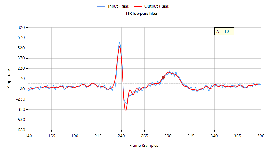
The following plot shows the filtering performance of a Chebyshev type I lowpass IIR on ECG data – input waveform (shown in blue) shifted by 10 samples (\(\small \Delta=10\)) to approximately compensate for the filter’s group delay. Notice that the filtered signal (shown in red) has attenuated, broadened and added oscillations around the ECG peak, which is undesirable.
In order for a digital filter to have linear phase, its impulse response must have conjugate-even or conjugate-odd symmetry about its midpoint. This is readily seen for an FIR filter,
With the following constraint on its coefficients,
which leads to,
Analysing Eqn. 3, we see that roots (zeros) of \(\small H(z)\) must also be the zeros of \(\small H^\ast (1/z^\ast)\). This means that the roots of \(\small H(z)\) must occur in conjugate reciprocal pairs, i.e. if \(\small z_k\) is a zero of \(\small H(z)\), then \(\small H^\ast (1/z^\ast)\) must also be a zero.
Why IIR filters do not have linear phase
A digital filter is said to be bounded input, bounded output stable, or BIBO stable, if every bounded input gives rise to a bounded output. All IIR filters have either poles or both poles and zeros, and must be BIBO stable, i.e.
\(\displaystyle \sum_{k=0}^{\infty}\left|h(k)\right|<\infty \tag{4}\)
Where, \(\small h(k)\) is the filter’s impulse response. Analyzing Eqn. 4, it should be clear that the BIBO stability criterion will only be satisfied if the system’s poles lie inside the unit circle, since the system’s ROC (region of convergence) must include the unit circle. Consequently, it is sufficient to say that a bounded input signal will always produce a bounded output signal if all the poles lie inside the unit circle.
The zeros on the other hand, are not constrained by this requirement, and as a consequence may lie anywhere on z-plane, since they do not directly affect system stability. Therefore, a system stability analysis may be undertaken by firstly calculating the roots of the transfer function (i.e., roots of the numerator and denominator polynomials) and then plotting the corresponding poles and zeros upon the z-plane.
Applying the developed logic to the poles of an IIR filter, we now arrive at a very important conclusion on why IIR filters cannot have linear phase.
A BIBO stable filter must have its poles within the unit circle, and as such in order to get linear phase, an IIR would need conjugate reciprocal poles outside of the unit circle, making it BIBO unstable.
Based upon this statement, it would seem that it’s not possible to design an IIR to have linear phase. However, a discussed below, phase equalisation filters can be used to linearise the passband phase response.
Phase linearisation with all-pass filters
All-pass phase linearisation filters (equalisers) are a well-established method of altering a filter’s phase response while not affecting its magnitude response. A second order (Biquad) all-pass filter is defined as:
Where, \(\small f_c\) is the centre frequency, \(\small r\) is radius of the poles and \(\small f_s\) is the sampling frequency. Notice how the numerator and denominator coefficients are arranged as a mirror image pair of one another. The mirror image property is what gives the all-pass filter its desirable property, namely allowing the designer to alter the phase response while keeping the magnitude response constant or flat over the complete frequency spectrum.
Cascading an APF (all-pass filter) equalisation cascade (comprised of multiple APFs) with an IIR filter, the basic idea is that we only need to linearise the phase response the passband region. The other regions, such as the transition band and stopband may be ignored, as any non-linearities in these regions are of little interest to the overall filtering result.
The challenge
The APF cascade sounds like an ideal compromise for this challenge, but in truth a significant amount of time and very careful fine-tuning of the APF positions is required in order to achieve an acceptable result. Each APF has two variables: \(\small f_c\) and \(\small r\) that need to be optimised, which complicates the solution. This is further complicated by the fact that the more APF stages that are added to the cascade, the higher the overall filter’s group delay (latency) becomes. This latter issue may become problematic for fast real-time closed loop control systems that rely on an IIR’s low latency property.
Nevertheless, despite these challenges, the APF equaliser is a good compromise for linearising an IIRs passband phase characteristics.
The APF equaliser
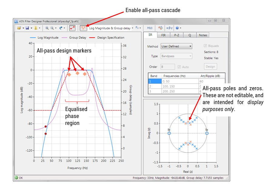
ASN Filter Designer provides designers with a very simple to use graphical all-phase equaliser interface for linearising the passband phase of IIR filters. As seen below, the interface is very intuitive, and allows designers to quickly place and fine-tune APF filters positions with the mouse. The tool automatically calculates \(\small f_c\) and \(\small r\), based on the marker position.
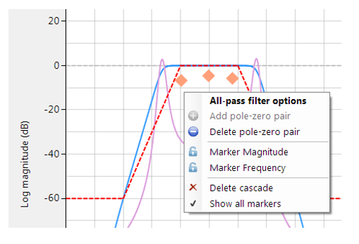
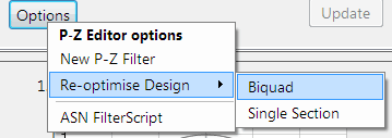
Right clicking on the frequency response chart or on an existing all-pass design marker displays an options menu, as shown on the left.
You may add up to 10 biquads (professional version only).
An IIR with linear passband phase
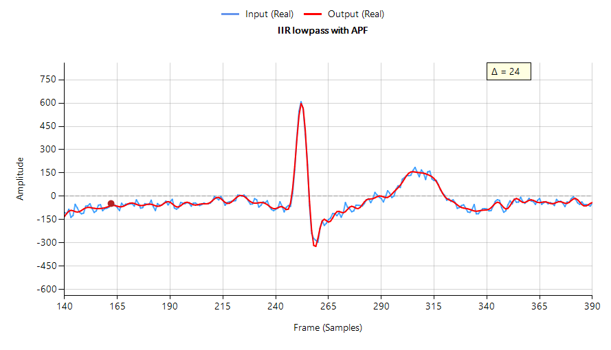
Designing an equaliser composed of three APF pairs, and cascading it with the Chebyshev filter of Figure 1, we obtain a filter waveform that has a much a sharper peak with less attenuation and oscillation than the original IIR – see below. However, this improvement comes at the expense of three extra Biquad filters (the APF cascade) and an increased group delay, which has now risen to 24 samples compared with the original 10 samples.
(minimal phase distortion)
The frequency response of both the original IIR and the equalised IIR are shown below, where the group delay (shown in purple) is the average delay of the filter and is a simpler way of assessing linearity.
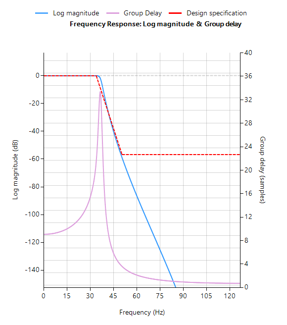
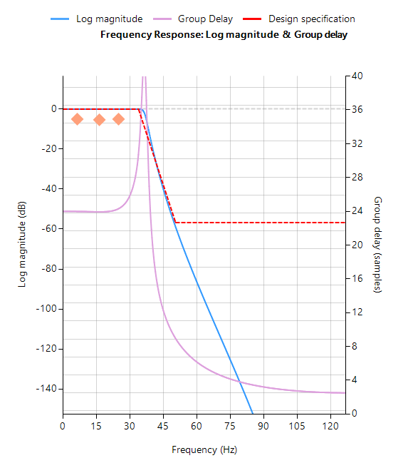
Notice that the group delay of the equalised IIR passband (shown on the right) is almost flat, confirming that the phase is indeed linear.
Automatic code generation to Arm processor cores via CMSIS-DSP
The ASN Filter Designer’s automatic code generation engine facilitates the export of a designed filter to Cortex-M Arm based processors via the CMSIS-DSP software framework. The tool’s built-in analytics and help functions assist the designer in successfully configuring the design for deployment.
Before generating the code, the IIR and equalisation filters (i.e. H1 and Heq filters) need to be firstly re-optimised (merged) to an H1 filter (main filter) structure for deployment. The options menu can be found under the P-Z tab in the main UI.
All floating point IIR filters designs should be based on Single Precision arithmetic and either a Direct Form I or Direct Form II Transposed filter structure, as this is supported by a hardware multiplier in the M4F, M7F, M33F and M55F cores. Although you may choose Double Precision, hardware support is only available in some M7F and M55F Helium devices. The Direct Form II Transposed structure is advocated for floating point implementation by virtue of its higher numerically accuracy.
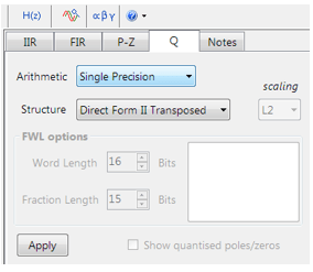
Quantisation and filter structure settings can be found under the Q tab (as shown on the left). Setting Arithmetic to Single Precision and Structure to Direct Form II Transposed and clicking on the Apply button configures the IIR considered herein for the CMSIS-DSP software framework.
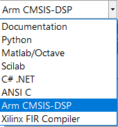
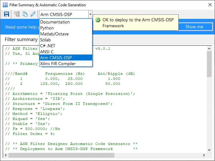
Select the Arm CMSIS-DSP framework from the selection box in the filter summary window:
The automatically generated C code based on the CMSIS-DSP framework for direct implementation on an Arm based Cortex-M processor is shown below:
The ASN Filter Designer’s automatic code generator generates all initialisation code, scaling and data structures needed to implement the linearised filter IIR filter via Arm’s CMSIS-DSP library.
Arm deployment wizard
Professional licence users may expedite the deployment by using the Arm deployment wizard. The built in AI will automatically determine the best settings for your design based on the quantisation settings chosen.
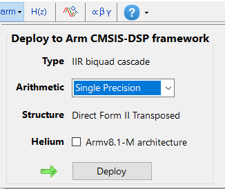
The built in AI automatically analyses your complete filter cascade and converts any H2 or Heq filters into an H1 for implementation.
What we have learnt
The roots of a linear phase digital filter must occur in conjugate reciprocal pairs. Although this no problem for an FIR filter, it becomes infeasible for an IIR filter, as poles would need to be both inside and outside of the unit circle, making the filter BIBO unstable.
The passband phase response of an IIR filter may be linearised by using an APF equalisation cascade. The ASN Filter Designer provides designers with everything they need via a very simple to use, graphical all-pass phase equaliser interface, in order to design a suitable APF cascade by just using the mouse!
The linearised IIR filter may be exported via the automatic code generator using Arm’s optimised CMSIS-DSP library functions for deployment on any Cortex-M microcontroller.

