Where ‘smart traffic’ has already 417 billion hits on google, I only found ‘smart air’ for a kind of door lock and ‘smart drone’ for an advanced toy drone. But definitely, drones are so hot that they will become part of something called ‘smart air’. The SESAR project predicts that drones will make 250 billion hours of flight in the European Union alone. For comparison: this is far more than the air traffic of ‘normal’ airplanes today.

Because drones are using many sensors, we did some research how the use of drones can grow to maturity and fuel ‘smart air’. Today we talk about challenges for delivery drones.

Delivery drones

No wonder, drones have proven to be very convenient already and have even more promises in store. Soon, it will be commonplace that drones are delivering packages, from hot pizzas to even more urgent medicines. And even humans: the first drone taxis are already being tested. At this moment, drones are already used for drag-and-drop deliveries in some rural and faraway areas. Most articles on the internet talk about the use in drones in big city areas. And there they have the big advantage of an -still- almost empty sky instead of congested roads and overfull parking places. For that, delivery by drones will be faster and more predictable.

But until use of drones are entirely tried and tested, most drone developments will take place on rural environments. Because here the risk of large damage is a lot smaller when something will go wrong. In time, delivery drones will still be used in rural places. Maybe as a standalone, maybe in combination with self-driving trucks. Reach will not be a big problem, since the whole word is getting connected fast. So, reach will almost only depend on battery endurance. And for now, these batteries have only a limited capacity for distance and cargo.

Challenges while travelling

Like all delivery services, drone delivery has to a pick-up a package, travel to the destination and drop-of the package.  While travelling, drones have to know how to reach their destination. Meanwhile, there are some challenges:

  • Risk of colliding, with other drones, birds and other air users. Just like other traffic
  • And at point in time, some traffic rules have to be set in place. Sensors can help to let the drone follow these rules
  • How drones can stay on course, even with wind
  • Preventing drones to cross over forbidden (known) areas and unexpected ‘wrong’ areas (e.g. a building or a wood on fire)
  • How to prevent a package from falling? How to alert that a package will probably fall? Or maybe the drone itself? If so, measurement can be taken. Already, there are experiments with self-destruction. But maybe more practical solutions can be found to let the drone aim for a ‘safe area’, such as a park, river, etc. for an ‘emergency landing’
  • Acceptance of drones beside safety: how to guarentee privacy when drones are flying over peopled areas? Then there is the issue of noise: research shows that people find the noise of drones one of the most annoying forms of noise

Challenges with dropping the cargo

For now, the drop-of is literally done by dropping-of the cargo. Maybe with the aid of a cord which places the package as soft as possible to the ground. But anyhow: the drone stays in the air. So, technology has to get safe: for the package to be delivered undamaged. How does the drone know that the right person gets the package? And we have to prevent dogs from biting the package. And of course, to prevent that the dropped cargo will harm humans, animals or buildings or even worse.

The use of sensors

The application possibilities of drones are very promising for delivery uses. It is still in its experimental phase. But with developments going fast, soon it will reach the maturity phase. For this, there are two-fold kind of challenges.

Some are challenges on privacy, safety and security. These challenges have to be solved before the use of drones will get widespread trust and acceptance. The other are technical and communication issues: where multiple drones are being used – especially in cities- challenges how drones can and have to behave in traffic has to be solved.

In both challenges, sensors play a pivotal role in solving the technical questions. In all cases, ASN Filter Designer can help with sensor measurement with real-time feedback and the powerful signal analyzer. How? Look at ASN Filter Designer or mail ASN consultancy: designs@advsolned.com

Do you agree with this list? Do you have other suggestions? Please let us know!

Typical challenges faced by assets managers include:

  • How to measure mechanical component fatigue?
  • How to assess electrical wiring health?
  • How to reduce overall operating costs, but not comprise on public safety?
  • Risks posed by hackers & terrorists
  • Asset damage due to vandalism

Preventative Maintenance aims to solve the aforementioned problems by acting pre-emptively. This is achieved by constantly monitoring the performance of critical components (usually with sensors) and then alerting the maintenance team that a component is about to fail. The asset management team can then schedule maintenance in order to replace the failing component(s) with minimum disruption to the public, and overall lower operational costs.

  • Plan maintenance
  • Machine health care
  • Motor health care
  • Secure firmware updates and anti-tampering

Plan maintenance

Monitoring the health of critical component, such as a lamp, motor or machine component and input power supply. Our algorithms and analytics help asset management departments provide planned maintenance.

A better maintenance program is achieved by constantly monitoring the performance of critical components (usually with sensors or other devices) and then alerting the maintenance team that a component is about to fail.

Machine health care

The health of a machine can be determined by ‘listening’ to the sound it makes via microphones. Algorithms filter and compare recorded audio to fingerprint templates of known failures.

Motor health care

The health of an industrial motor be determined by analysis the phase currents. Algorithms filter and compare captured data to fingerprints templates of known failures. The phase current data can also be used to check for wire breaks or phase failure.

Secure firmware updates & Anti-tampering

ASN’s security module provides asset protection up to military grade, and while at the same time allowing for secure (encrypted) firmware updates.

ASN contactless measurement, smart algorithms and alerting offers the ideal condition for this programme. The asset management team can then schedule maintenance in order to replace the failing component(s) with minimum disruption to the public, and overall lower operational costs.

Let’s make an appointment to see how can help you create an effective maintenance programme and reduce your Total Cost of Ownership.

Industrial induction motors are found everywhere: Lifts, escalators, cable cars, water sluices, cranes, and even washing machines etc. Motors form the backbone of these devices. Since they are mission critical, a failure of a motor may disrupt the whole production line, crippling your precious infrastructure as a whole. As an example: if the motor fails on a water sluice, the disruption means that ships can’t deliver their cargo on time. Our experience has shown that with preventative motor maintenance, you can save up to 51% of your maintenance budget!

Common sources of industrial motor failure

Of course, each industrial motor has its own characteristics. However, common sources of failure in an industrial induction motor are:

  • Ball bearing and rotor crack/break
  • Stator winding faults
  • Rotor winding faults (rotor bars, end-rings etc.)

Save up to 51% with preventative maintenance

For public infrastructure, industrial motors are mission critical. They need to be regularly be checked under expensive maintenance programmes. With ASN’s IoT solutions, you can predict and prevent equipment failure by monitoring product wear and replacement rates.  And if you recognize a slight disturbance, you can solve them easily. Before little faults have become big and expensive problems. When little faults are recognized, they can be repaired without any signifcant downtime. At a time it suits your client best. As such, you can improve the reliability of your assets and reduce downtime.

Effective and efficient use of an engineer’s precious time

Motor health care starts with sensors. With these sensors, you can monitor the running of your monitors automatically by placing sensors in the vicinity of your motors. When a signal pops up that there might be a problem, an engineer can repair this motor. Previously, engineers did their inspection rounds, giving every motor the same attention. Now, engineers can focus on motors that really need attention.

With preventative maintenance, your customers  can save a fortune and minimise any disruption to service. You can save up to 51% on your maintenance costs with our Preventative Maintenance solutions. They are based on safe contactless sensor measurement, and optimize the life expectancy of your industrial motor. Learn more at: https://www.advsolned.com/motor-health-care/ or drop us a line at: info@advsolned.com

A leading coffee manufacturer wanted to add a function to their coffee machines that could fill every kind of mug (small, large, glass, ceramic) fully or half-fully. The requirement was that system must be able to automatically find the dimensions of the mug and track the filling process in real-time without human intervention.

A lot of time is wasted due to coffee spills due to overfilled coffee mugs, but the challenge was to see if this could be done for a reasonably low cost – around 10 EUR.

As no other coffee machine manufacturer had a flexible solution for their coffee machines, this would give them a competitive advantage as well as add a exciting new gadget to their product portfolio.

Find out how we solved this challenge here: coffee drinks dispenser case

Until now, the professional use of drones is mostly still in an experimenting stage. However, drones are one of the golden nuggets in IoT because they can play a pivotal role, for instance in congested cities and faraway areas for delivery. Further, they can be a great help to give an overview of a large area or for places which are difficult or dangerous to reach.

In one of our previous blogs, we concluded that sensor measurement has mostly been a case of trial and error. In this blog, we list some of the challenges we see for sensor measurement which has to be solved to bring the professional use of drones to full maturity.

Practical challenges which can and must be solved with sensors

Here are some of the challenges we have found:

  • Risk of colliding, with other drones, birds and other air users. Just like other traffic
  • And at point in time, some traffic rules have to be set in place. Sensors can help to let the drone follow these rules
  • How drones can stay on course, even with wind
  • Preventing drones to cross over forbidden (known) areas and unexpected ‘wrong’ areas (e.g. a building or a wood on fire)
  • Challenges with unloading the package:
    • Without damage
    • Without harming people, animals, buildings
    • How the drone will know that the right person gets the package? Can we prevent dogs from biting the package?
  • How to prevent a package from falling? How to alert that a package will probably fall? Or maybe the drone itself? If so, measurement can be taken. Already, there are experiments with self-destruction. But maybe more practical solutions can be found to let the drone aim for a ‘safe area’, such as a park, river, etc. for an ‘emergency landing’.

In all cases, ASN Filter Designer can help with sensor measurement with real-time feedback and the powerful signal analyser? How? Look at ASN Filter Designer or mail us: info@advsolned.com

Do you agree with this list? Do you have other suggestions? Please let us know!

Upgrading legacy designs based on analog filters

Analog filters have been around since the beginning of electronics, ranging from simple inductor-capacitor networks to more advanced active filters with op-amps. As such, there is a rich collection of tried and tested legacy filter designs for a broad range of sensor measurement applications. However, with the performance requirements of modern IoT (Internet of Things) sensor measurement applications and lower product costs, digital filters integrated into the microcontroller’s application code are becoming the norm, but how can we get the best of both worlds?

Rather than re-inventing the wheel, product designers can take an existing analog filter transfer function, transform it to digital (via a transform) and implement it as digital filter in a microcontroller or DSP (digital signal processor). Although  analog-to-digital transforms have been around for decades, the availability of DSP design tooling for tweaking the ‘transformed digital filter’ has been somewhat limited, hindering the design and validation process.

A 2nd order analog lowpass filter is shown below, and in its simplest form, only 5 components are required to build the filter, which sounds easy. Right?
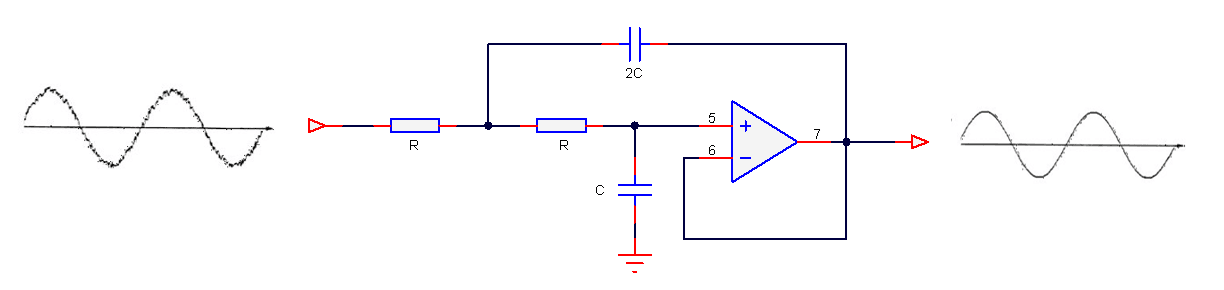
2nd order analog lowpass filter

The pros

The most obvious advantage is that analog filters have an excellent resolution, as there are no ‘number of bits’ to consider. Analog filters have good EMC (electromagnetic compatibility) properties as there is no clock generating noise. There are no effects of aliasing, which is certainly true for the simpler op-amps, which don’t have any fancy chopping or auto-calibration circuitry built into them, and analog designs can be cheap which is great for cost sensitive applications.

Sound great, but what’s the bad news?

Analog filters have several significant disadvantages that affect filter performance, such as component aging, temperature drift and component tolerance. Also, good performance requires good analog design skills and good PCB (printed circuit board) layout, which is hard to find in the contemporary skills market.

These disadvantages make digital filters much more attractive for modern applications, that require high repeatability of characteristics.  Looking at an example, let’s say that you want to manufacture 1000 measurement modules after optimising your filter design. With a digital solution you can be sure that the performance of your filter will be identical in all modules. This is certainly not the case with analog, as component tolerance, component aging and temperature drift mean that each module’s filter will have its own characteristics. Also, an analog filter’s frequency response remains fixed, i.e. a Butterworth filter will always be a Butterworth filter – any changes the frequency response would require physically changing components on the PCB – not ideal!

Digital filters are adaptive and flexible, we can design and implement a filter with any frequency response that we want, deploy it and then update the filter coefficients without changing anything on the PCB! It’s also easy to design digital filters with linear phase and at very low sampling frequencies – two things that are tricky with analog.

Laplace to discrete/digital transforms

The three methods discussed herein essentially involve transforming a Laplace (analog) transfer function, \(H(s)\) into a discrete transfer function, \(H(z)\) such that a tried and tested analog filter that is already used in a design may be implemented on a microcontroller or DSP.

A selection of some useful Laplace to z-transforms are given in table below:

\(
\begin{array}{ccc}\hline
H(s) &\longleftrightarrow & H(z) \\ \hline
1 &\longleftrightarrow & 1 \\
\frac{\displaystyle1}{\displaystyle s}
&\longleftrightarrow& \frac{\displaystyle 1}{\displaystyle 1-z^{\scriptstyle -1}}\\
\frac{\displaystyle 1}{\displaystyle s^{\scriptstyle 2}} &\longleftrightarrow& \frac{\displaystyle
Tz^{\scriptstyle-1}}{\displaystyle (1-z^{\scriptstyle -1})^2}\\
\frac{\displaystyle 1}{\displaystyle s+a}
&\longleftrightarrow&
\frac{\displaystyle 1}{\displaystyle 1-e^{-aT}z^{-1}}\\
\frac{\displaystyle 1}{\displaystyle (s+a)^2}
&\longleftrightarrow& \frac{\displaystyle z^{-1}(1-e^{-aT})}{\displaystyle a(1-z^{-1})(1-e^{-aT}z^{-1})}\\\hline
\end{array}
\)
A table of useful Laplace and z-transforms

The Bilinear z-transform (BZT)

The Bilinear z-transform (BZT), simply converts an analog transfer function, \(H(s)\) into a discrete transfer function, \(H(z)\) by replacing all \(s\) terms with the following:

\(\displaystyle
s=\frac{2}{T}\frac{1-z^{-1}}{1+z^{-1}} \label{bzt}\)

where, \(T\) is the discrete system’s sampling period. However, substituting \(s=j\Omega\) and \(z=e^{jwT}\) into the BZT equation and simplifying, notice that there is actually a non-linear relationship between the analog, \(\Omega\) and discrete, \(w\) frequencies. This relationship is shown below, and is due to the nonlinearity of the arctangent function.

\(\displaystyle\omega=2\tan^{-1}\left(\frac{\Omega T}{2}\right)\label{bzt_warp_def1}\)

Analysing the equation, it can be seen that the equally spaced  analog frequencies in the range \( -\infty\lt\Omega\lt\infty\) are nonlinearly compressed in the frequency range \( -\pi\lt w\lt\pi\) in the discrete domain. This relationship is referred to as frequency warping, and may be compensated for by pre-warping the analog frequencies by:

\(\displaystyle
\Omega_c=\frac{2}{T}\tan\left(\frac{\Omega_d T}{2}\right)
\label{bzt_warp_def2}
\)

where, \(\displaystyle\Omega_c\) is the compensated or pre-warped analog frequency, and \(\displaystyle\Omega_d\) is the desired analog frequency.

The ASN FilterScript command \(\texttt{bilinear}\) may be used convert a Laplace transfer function into its discrete equivalent using the BZT transform. An example is given below.

The Impulse Invariant Transform

The second transform, is referred to as the impulse invariant transform (IIT), since the poles of the Laplace transfer function are converted into their discrete equivalents, such that the discrete impulse response, \(h(n)\) is identical to a regularly sampled representation of the analog impulse response (i.e., \(h(n)=h(nT)\), where \(T\) is the sampling rate, and \(t=nT\)). The IIT is a much more tedious transformation technique than the BZT, since the Laplace transfer function must be firstly expanded using partial fractions before applying the transform.

The transformation technique is defined below:

\(\displaystyle
\frac{K}{s+a} \quad\longrightarrow\quad
\frac{K}{1-e^{-aT}z^{-1}} \label{iit_def}
\)

This method suffers from several constraints, since it does not allow for the transformation of zeros or individual constant terms (once expanded), and must have a high sampling rate in order to overcome the effects of spectral aliasing. Indeed, the effects of aliasing hinder this method considerably, such that the method should only be used when the requirement is to match the analog transfer function’s impulse response, since the resulting discrete model may have a different magnitude and phase spectrum (frequency response) to that of the original analog system. Consequently, the impulse invariant method is unsuitable for modelling highpass filters, and is therefore limited to the modelling of lowpass or bandpass type filters.

Due to the aforementioned limitations of the IIT method, it is currently not supported in ASN Filterscript.

The Matched-z transformation

Another analog to discrete modelling technique is the matched-z transformation. As the name suggests, the transform converts the poles and zeros from the analog transfer function directly into poles and zeros in the z-plane. The transformation is described below, where \(T\) is the sampling rate.

\(\displaystyle
\frac{\prod\limits_{k=1}^q(s+b_k)}{\prod\limits_{k=1}^p(s+a_k)}
\quad\longrightarrow\quad
\frac{\prod\limits_{k=1}^q(1-e^{-b_kT}z^{-1})}{\prod\limits_{k=1}^p(1-e^{-a_kT}z^{-1})}
\label{matchedz_def}
\)

Analysing the transform equation, it can be seen that the transformed z-plane poles will be identical to the poles obtained with the impulse invariant method. However, notice that the positions of the zeros will be different, since the impulse invariant method cannot transform them.

The ASN Filterscript command \(\texttt{mztrans}\) is available for this method.

A detailed example

In order to demonstrate the ease of transforming analog filters into their discrete/digital equivalents using the analog to discrete transforms, an example of modelling with the BZT will now follow for a 2nd order lowpass analog filter.

A generalised 2nd order lowpass analog filter is given by:

\(\displaystyle
H(s)=\frac{w_c^2}{s^2+2\zeta w_c s + w_c^2}
\)

where, \(w_c=2\pi f_c\) is the cut-off frequency and \(\zeta\) sets the damping of the filter,  where a  \(\zeta=1/\sqrt{2}\) is said to be critically damped or equal to -3dB at \(w_c\). Many analog engineers choose to specify a quality factor, \(Q =  \displaystyle\frac{1}{2\zeta}\) or peaking factor for their designs. Substituting \(Q\) into \(H(s)\), we obtain:

\(\displaystyle
H(s)=\frac{w_c^2}{s^2+ \displaystyle{\frac{w_c}{Q}s} + w_c^2}
\)

Analysing, \(H(s)\) notice that \(Q=1/\sqrt{2} = 0.707\) also results in a critically damped response. Various values of \(Q\) are shown below, and as seen when \(Q>1/\sqrt{2}\) peaking occurs.

Values of Q

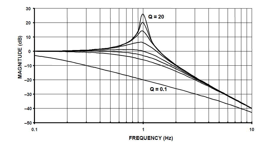
2nd order lowpass filter prototype magnitude spectrum for various value of Q:
notice that when \(Q>1/\sqrt{2}\) peaking occurs.

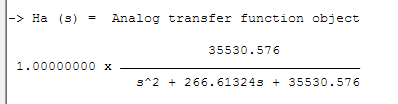
Before applying the BZT in ASN FilterScript, the analog transfer function must be specified in an analog filter object. The following code sets up an analog filter object for the 2nd order lowpass prototype considered herein:

Main()

wc=2*pi*fc;
Nb={0,0,wc^2};
Na={1,wc/Q,wc^2};

Ha=analogtf(Nb,Na,1,"symbolic"); // make analog filter object

The \(\texttt{symbolic}\) keyword generates a symbolic transfer function representation in the command window. For a sampling rate of \(f_s=500Hz\) and \(f_c=30Hz\) and \(Q=0.707\), we obtain:

ASN FilterScript analog command

Applying the BZT via the \(\texttt{bilinear}\) command without prewarping,

 Hd=bilinear(Ha,0,"symbolic"); 

bilinear transformation

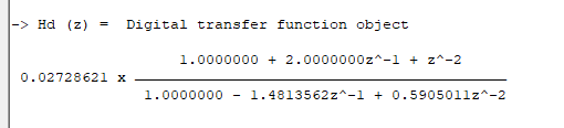
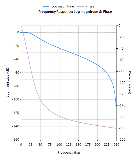
The complete frequency response of the transformed digital filter is shown below, where it can be seen that the at \(30Hz\) the magnitude is \(-3dB\) and the phase is \( -90^{\circ}\), which is as expected. Notice also how the filter’s magnitude roll-off  is affected by the double zero pair at Nyquist (see the z-plane chart below), leading to differences from its analog cousin. Pole-zero chart 2nd order LPF

2nd order LPF

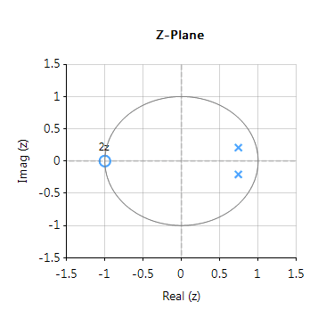
The pole-zero positions may be tweaked within ASN Filterscript or via the ASN Filter Designer’s interactive pole-zero z-plane plot editor by just using the mouse!

Implementation

The complete code for transforming a generalised 2nd order analog  lowpass filter prototype into its digital equivalent using the BZT via ASN FilterScript is given below:


ClearH1;  // clear primary filter from cascade
interface Q = {0.1,10,0.02,0.707};
interface fc = {10,200,10,40};

Main()

wc=2*pi*fc;
Nb={0,0,wc^2};
Na={1,wc/Q,wc^2};

Ha=analogtf(Nb,Na,1,"symbolic"); // make analog filter object
Hd=bilinear(Ha,0,"symbolic"); // transform Ha via BZT into digital object, Hd

Num=getnum(Hd);
Den=getden(Hd);
Gain=getgain(Hd);

ASN Filter Designer Box

Download demo now

Licencing information


Author

  • Dr. Sanjeev Sarpal

    Sanjeev is an AIoT visionary and expert in signals and systems with a track record of successfully developing over 25 commercial products. He is an Arm Ambassador and advises top international blue chip companies on their AIoT solutions and strategies for I4.0, telemedicine, smart healthcare, smart grids and smart buildings.

Motor producers are beginning to see that they can add value through preventative maintenance. However, when we speak to motor producers, sometimes companies begin to laugh when we ask them if they deliver health care monitoring through sensors to their customers already. They think that preventative maintenance is an enemy of their motor production:

“if motors can be made to run longer, we have less to sell”.

And sometimes companies just look glassy-eyed:

“We’re an old-fashioned company”.

Customers want you to deliver solutions, not motors

This is old fashioned thinking indeed. And like every other lagged thinking, these companies will get obsolete.  In old days, you could sell a ‘product’ with features such and such. Nowadays, customers are solely interested in the solution a company delivers. Customers want their business to run smoothly and without downtime. In this way of thinking, a motor is not a thing with a rotor, bearings and such, but it is a means which guarantees that a whole production line runs smoothly and without interruption.

Safe and sound running motors makes a customer satisfied

So, customers are more satisfied when their motor is running properly. And when it begins not to run properly, they want to know beforehand before a slight disturbance has become a real problem. When they know beforehand, they can take proper action on time, which means lesser costs and in most cases without downtime or at least as short as possible. Because downtime affects the production line in the whole. When the motor has really problems, your customer is forced to get their production on hold for a long time. Then customers not only have to face bigger repair costs. But mostly, costs are higher because now the whole production line has fallen out.

Motor health care starts with sensors

By placing sensors in the vicinity of your motors or even building them in, you can monitor the running of your motors automatically. When a signal pops up that there might be a problem, an engineer can repair this motor. This is also the modern way: previously, engineers did their rounds of motor inspections, giving every motor attention. Now, engineers can focus on motors that need attention.

At Advanced Solutions Nederland, we can help you to deliver real solutions to your customers once again. Visit: https://www.advsolned.com/motor-health-care/ or drop us a line at: info@advsolned.com