Posts

Een Peaking of Bell filter is een type geluidsequalisatiefilter dat de grootte van een bepaalde set frequenties rond een centrumfrequentie versterkt of verzwakt om zo de magnitude van het geluid te egaliseren. Zoals te zien is in de grafiek hieronder, ontleent het filter zijn naam aan de vorm van het magnitudenspectrum (blauwe lijn) dat lijkt op een Bell-curve.

Peaking filter or Bell filter, a type of audio equalisation filter that boosts or attenuates the magnitude of a specified set of frequencies around a centre frequency in order to perform magnitude equalisation. As seen in the plot in the below, the filter gets its name from the shape of the its magnitude spectrum (blue line) which resembles a Bell curve.

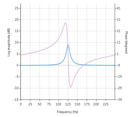
Frequentierespons (magnitude weergegeven in blauw, fase weergegeven in paars) van een 2e orde Bell-filter met een piek bij 125 Hz

All-pass filters

Centraal in het Bell-filter staat het zogenaamde All-pass filter. All-pass filters bieden een eenvoudige manier om de faserespons van een IIR te wijzigen/verbeteren zonder de grootte van de IIR te beïnvloeden. Als zodanig worden ze meestal aangeduid als fase-equalizers en hebben ze een bijzondere toepassing gevonden in digitale audiotoepassingen.

Een tweede orde all-pass filter is gedefinieerd als:

\( A(z)=\Large\frac{r^2-2rcos \left( \frac{2\pi f_c}{fs}\right) z^{-1}+z^{-2}}{1-2rcos \left( \frac{2\pi f_c}{fs}\right)z^{-1}+r^2 z^{-2}} \)

Merk op hoe de teller- en noemercoëfficiënten in spiegelbeeldig van elkaar zijn gerangschikt. De eigenschap van dit spiegelbeeld is wat de all-pass filter zijn gewenste eigenschap geeft, namelijk de ontwerper in staat stellen om de faserespons te veranderen terwijl de magnituderespons constant of vlak blijft over het volledige frequentiespectrum.

Een Bell filter kan worden geconstrueerd uit de \(A(z)\) filter door de volgende transferfunctie:

\(H(z)=\Large\frac{(1+K)+A(z)(1-K)}{2}\)

Na enige algebraïsche vereenvoudiging krijgen we de transferfunctie voor de Peaking of Bell filter als:

\(H(z)=\Large{\frac{1}{2}}\left[\normalsize{(1+K)} + \underbrace{\Large\frac{k_2 + k_1(1+k_2)z^{-1}+z^{-2}}{1+k_1(1+k_2)z^{-1}+k_2 z^{-2}}}_{all-pass filter}\normalsize{(1-K)} \right] \)

  • \(K\) wordt gebruikt om de gain en het teken van de piek in te stellen
  • \(k_1\) stelt de piek middenfrequentie in
  • \(k_2\) stelt de bandbreedte van de piek in

Implementatie

Een Bell filter kan gemakkelijk ASN FilterScript worden geimplementeerd:

ClearH1;  // clear primary filter from cascade
interface BW = {0,2,0.1,0.5}; // filter bandwidth
interface fc = {0, fs/2,fs/100,fs/4}; // peak/notch centre frequency
interface K = {0,3,0.1,0.5}; // gain/sign

Main()

k1=-cos(2*pi*fc/fs);
k2=(1-tan(BW/2))/(1+tan(BW/2));

Pz = {1,k1*(1+k2),k2}; // define denominator coefficients
Qz = {k2,k1*(1+k2),1}; // define numerator coefficients
Num = (Pz*(1+K) + Qz*(1-K))/2;
Den = Pz;
Gain = 1;

Deze code kan nu gebruikt worden om een geschikt Bell filter te ontwerpen, waarbij de exacte waardes van \(K, f_c\) en \(BW\) gemakkelijk kunnen worden gevonden door de interface variabelen te tweaken waarbij het resultaat in real-time te zien is, zoals hieronder weergegeven.

Directe aanpassingen in filter ontwerp

Bij de interactiviteit van de FilterScript IDE (geïntegreerde ontwikkelomgeving) staan de zogenaamde interfacevariabelen centraal. Een interface variabele wordt eenvoudigweg genoemd: een scalaire invoervariabele die gebruikt kan worden om een symbolische expressie te wijzigen zonder dat de code opnieuw gecompileerd hoeft te worden – dit stelt ontwerpers in staat om ‘on the fly’ te ontwerpen en snel tot een optimale oplossing te komen.

Zoals in het codevoorbeeld hierboven te zien is, moeten de interfacevariabelen worden gedefinieerd in de initialisatiesectie van de code, en kunnen ze constanten (zoals fs and pi) en eenvoudige wiskundige operatoren, zoals vermenigvuldigen * en /delen, bevatten. Dit wanneer het toevoegen van functies aan een interfacevariabele niet wordt ondersteund.

Een interfacevariabele wordt gedefinieerd als een vectorexpressie:

interface name = {minimum, maximum, step_size, default_value};

Waarbij alle vermeldingen echte scalaire waarden moeten zijn. Vectoren en complexe waarden worden niet gecompileerd.

Real-time updates

Alle interfacevariabelen worden gewijzigd via de interfacevariabele regelaar GUI. Na het compileren van de code gebruikt u de interface variabele controller om de waarden van de interface variabelen te tweaken en de effecten op de overdrachtsfunctie te zien. Als u test op live audio, kunt u een geladen audiobestand streamen en de interfacevariabelen in real-time aanpassen om de effecten van de nieuwe instellingen te horen.

A  Peaking or Bell filter is a type of audio equalisation filter that boosts or attenuates the magnitude of a specified set of frequencies around a centre frequency in order to perform magnitude equalisation. As seen in the plot in the below, the filter gets its name from the shape of the its magnitude spectrum (blue line) which resembles a Bell curve.

Peaking filter or Bell filter, a type of audio equalisation filter that boosts or attenuates the magnitude of a specified set of frequencies around a centre frequency in order to perform magnitude equalisation. As seen in the plot in the below, the filter gets its name from the shape of the its magnitude spectrum (blue line) which resembles a Bell curve.

Frequency response (magnitude shown in blue, phase shown in purple) of a 2nd order Bell filter peaking at 125Hz.

All-pass filters

Central to the Bell filter is the so called All-pass filter. All-pass filters provide a simple way of altering/improving the phase response of an IIR without affecting its magnitude response. As such, they are commonly referred to as phase equalisers and have found particular use in digital audio applications.

A second order all-pass filter is defined as:

\( A(z)=\Large\frac{r^2-2rcos \left( \frac{2\pi f_c}{fs}\right) z^{-1}+z^{-2}}{1-2rcos \left( \frac{2\pi f_c}{fs}\right)z^{-1}+r^2 z^{-2}} \)

Notice how the numerator and denominator coefficients are arranged as a mirror image pair of one another.  The mirror image property is what gives the all-pass filter its desirable property, namely allowing the designer to alter the phase response while keeping the magnitude response constant or flat over the complete frequency spectrum.

A Bell filter can be constructed from the \(A(z)\) filter by the following transfer function:

\(H(z)=\Large\frac{(1+K)+A(z)(1-K)}{2}\)

After some algebraic simplication, we obtain the transfer function for the Peaking or Bell filter as:

\(H(z)=\Large{\frac{1}{2}}\left[\normalsize{(1+K)} + \underbrace{\Large\frac{k_2 + k_1(1+k_2)z^{-1}+z^{-2}}{1+k_1(1+k_2)z^{-1}+k_2 z^{-2}}}_{all-pass filter}\normalsize{(1-K)} \right] \)

  • \(K\) is used to set the gain and sign of the peak
  • \(k_1\) sets the peak centre frequency
  • \(k_2\) sets the bandwidth of the peak

Implementation

A Bell filter may easily be implemented in ASN FilterScript as follows:

ClearH1;  // clear primary filter from cascade
interface BW = {0,2,0.1,0.5}; // filter bandwidth
interface fc = {0, fs/2,fs/100,fs/4}; // peak/notch centre frequency
interface K = {0,3,0.1,0.5}; // gain/sign

Main()

k1=-cos(2*pi*fc/fs);
k2=(1-tan(BW/2))/(1+tan(BW/2));

Pz = {1,k1*(1+k2),k2}; // define denominator coefficients
Qz = {k2,k1*(1+k2),1}; // define numerator coefficients
Num = (Pz*(1+K) + Qz*(1-K))/2;
Den = Pz;
Gain = 1;

This code may now be used to design a suitable Bell filter, where the exact values of \(K, f_c\) and \(BW\) may be easily found by tweaking the interface variables and seeing the results in real-time, as described below.

Designing the filter on the fly

Central to the interactivity of the FilterScript IDE (integrated development environment) are the so called interface variables. An interface variable is simply stated: a scalar input variable that can be used modify a symbolic expression without having to re-compile the code – allowing designers to design on the fly and quickly reach an optimal solution.

As seen in the code example above, interface variables must be defined in the initialisation section of the code, and may contain constants (such as, fs and pi) and simple mathematical operators, such as multiply * and / divide. Where, adding functions to an interface variable is not supported.

An interface variable is defined as vector expression:

interface name = {minimum, maximum, step_size, default_value};

Where, all entries must be real scalars values. Vectors and complex values will not compile.

Real-time updates

All interface variables are modified via the interface variable controller GUI. After compiling the code, use the interface variable controller to tweak the interface variables values and see the effects on the transfer function. If testing on live audio, you may stream a loaded audio file and adjust the interface variables in real-time in order to hear the effects of the new settings.