A Peaking or Bell filter is a type of audio equalisation filter that boosts or attenuates the magnitude of a specified set of frequencies around a centre frequency in order to perform magnitude equalisation. As seen in the plot in the below, the filter gets its name from the shape of the its magnitude spectrum (blue line) which resembles a Bell curve.
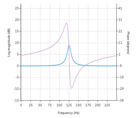
Frequency response (magnitude shown in blue, phase shown in purple) of a 2nd order Bell filter peaking at 125Hz.
All-pass filters
Central to the Bell filter is the so called All-pass filter. All-pass filters provide a simple way of altering/improving the phase response of an IIR without affecting its magnitude response. As such, they are commonly referred to as phase equalisers and have found particular use in digital audio applications.
A second order all-pass filter is defined as:
\( A(z)=\Large\frac{r^2-2rcos \left( \frac{2\pi f_c}{fs}\right) z^{-1}+z^{-2}}{1-2rcos \left( \frac{2\pi f_c}{fs}\right)z^{-1}+r^2 z^{-2}} \)
Notice how the numerator and denominator coefficients are arranged as a mirror image pair of one another. The mirror image property is what gives the all-pass filter its desirable property, namely allowing the designer to alter the phase response while keeping the magnitude response constant or flat over the complete frequency spectrum.
A Bell filter can be constructed from the \(A(z)\) filter by the following transfer function:
\(H(z)=\Large\frac{(1+K)+A(z)(1-K)}{2}\)
After some algebraic simplication, we obtain the transfer function for the Peaking or Bell filter as:
\(H(z)=\Large{\frac{1}{2}}\left[\normalsize{(1+K)} + \underbrace{\Large\frac{k_2 + k_1(1+k_2)z^{-1}+z^{-2}}{1+k_1(1+k_2)z^{-1}+k_2 z^{-2}}}_{all-pass filter}\normalsize{(1-K)} \right] \)
- \(K\) is used to set the gain and sign of the peak
- \(k_1\) sets the peak centre frequency
- \(k_2\) sets the bandwidth of the peak
Implementation
A Bell filter may easily be implemented in ASN FilterScript as follows:
ClearH1;  // clear primary filter from cascade
interface BW = {0,2,0.1,0.5}; // filter bandwidth
interface fc = {0, fs/2,fs/100,fs/4}; // peak/notch centre frequency
interface K = {0,3,0.1,0.5}; // gain/sign

Main()

k1=-cos(2*pi*fc/fs);
k2=(1-tan(BW/2))/(1+tan(BW/2));

Pz = {1,k1*(1+k2),k2}; // define denominator coefficients
Qz = {k2,k1*(1+k2),1}; // define numerator coefficients
Num = (Pz*(1+K) + Qz*(1-K))/2;
Den = Pz;
Gain = 1;
This code may now be used to design a suitable Bell filter, where the exact values of \(K, f_c\) and \(BW\) may be easily found by tweaking the interface variables and seeing the results in real-time, as described below.
Designing the filter on the fly
Central to the interactivity of the FilterScript IDE (integrated development environment) are the so called interface variables. An interface variable is simply stated: a scalar input variable that can be used modify a symbolic expression without having to re-compile the code – allowing designers to design on the fly and quickly reach an optimal solution.
As seen in the code example above, interface variables must be defined in the initialisation section of the code, and may contain constants (such as, fs and pi) and simple mathematical operators, such as multiply * and / divide. Where, adding functions to an interface variable is not supported.
An interface variable is defined as vector expression:
interface name = {minimum, maximum, step_size, default_value};
Where, all entries must be real scalars values. Vectors and complex values will not compile.
[arve mp4=”https://www.advsolned.com/wp-content/uploads/2018/07/peakingfilter.mp4″ align=”right” loop=”true” autoplay=”true” nodownload nofullscreen noremoteplayback… /]
Real-time updates
All interface variables are modified via the interface variable controller GUI. After compiling the code, use the interface variable controller to tweak the interface variables values and see the effects on the transfer function. If testing on live audio, you may stream a loaded audio file and adjust the interface variables in real-time in order to hear the effects of the new settings.
